前言
MPLS (Multi-Protocol Label Switching) 的概念是在一個封包之中加入 Label (標籤),所謂 Label,是加在 Layer 2 Header 與 Layer3 Header 之間的一串 32 bits 標示 (所以 MPLS 又稱為 Layer 2.5),其中 20bits 為 Label 值。路由器會依據這個 Label 值去判斷封包的 Next Hop,用了這個方法,路由器不用再查找 Route Table 便可以決定怎樣處理封包,傳送效率便可大大提升,此技術於 ISP 的 Backbone Network 中被廣泛使用。
傳統 Routing 處理
現在使用以下的網絡作例子,解釋傳統 Routing 的處理:
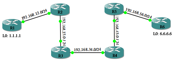
假設所有 Router 已經設定好 OSPF 作為 Routing Protocol。R1 的 L0:1.1.1.1 能夠 PING 通 R6 的 L0:6.6.6.6,但究竟每隻 Router 中間發生了什麼事呢?
R1#ping 6.6.6.6 source 1.1.1.1

 Type escape sequence to abort.
 Sending 5, 100-byte ICMP Echos to 6.6.6.6, timeout is 2 seconds:
 Packet sent with a source address of 1.1.1.1
 !!!!!
 Success rate is 100 percent (5/5), round-trip min/avg/max = 168/193/232 ms
當 R1 想 PING 6.6.6.6,它會查看自己的 Route Table,找最合適 (Longest Match) 的一條 Route 到達 6.6.6.6,發現 Next Hop 是 192.168.12.2。
R1#show ip route | begin Gateway
 Gateway of last resort is not set

 C    192.168.12.0/24 is directly connected, Ethernet0/0
      1.0.0.0/24 is subnetted, 1 subnets
 C       1.1.1.0 is directly connected, Loopback0
 O    192.168.45.0/24 [110/40] via 192.168.12.2, 00:21:43, Ethernet0/0
      6.0.0.0/32 is subnetted, 1 subnets
 O       6.6.6.6 [110/51] via 192.168.12.2, 00:21:43, Ethernet0/0
 O    192.168.56.0/24 [110/50] via 192.168.12.2, 00:21:43, Ethernet0/0
 O    192.168.23.0/24 [110/20] via 192.168.12.2, 00:21:43, Ethernet0/0
 O    192.168.34.0/24 [110/30] via 192.168.12.2, 00:21:43, Ethernet0/0
這時候 R1 會再做一次查找 Route Table 的動作去找出到達 192.168.12.2 的 Route。然後把封包丟出 Ethernet0/0,即是連接 R2 的 Interface。
R1#show ip route | begin Gateway
 Gateway of last resort is not set

 C    192.168.12.0/24 is directly connected, Ethernet0/0
      1.0.0.0/24 is subnetted, 1 subnets
 C       1.1.1.0 is directly connected, Loopback0
 O    192.168.45.0/24 [110/40] via 192.168.12.2, 00:21:43, Ethernet0/0
      6.0.0.0/32 is subnetted, 1 subnets
 O       6.6.6.6 [110/51] via 192.168.12.2, 00:21:43, Ethernet0/0
 O    192.168.56.0/24 [110/50] via 192.168.12.2, 00:21:43, Ethernet0/0
 O    192.168.23.0/24 [110/20] via 192.168.12.2, 00:21:43, Ethernet0/0
 O    192.168.34.0/24 [110/30] via 192.168.12.2, 00:21:43, Ethernet0/0
當 R2 收到這個封包,也做著相同的動作,查看自己的 Route Table,再丟到 R3,如此類推。
R2#show ip route | begin Gateway
 Gateway of last resort is not set

 C    192.168.12.0/24 is directly connected, Ethernet0/1
      1.0.0.0/32 is subnetted, 1 subnets
 O       1.1.1.1 [110/11] via 192.168.12.1, 00:27:23, Ethernet0/1
 O    192.168.45.0/24 [110/30] via 192.168.23.3, 00:27:23, Ethernet0/0
      6.0.0.0/32 is subnetted, 1 subnets
 O       6.6.6.6 [110/41] via 192.168.23.3, 00:27:23, Ethernet0/0
 O    192.168.56.0/24 [110/40] via 192.168.23.3, 00:27:23, Ethernet0/0
 C    192.168.23.0/24 is directly connected, Ethernet0/0
 O    192.168.34.0/24 [110/20] via 192.168.23.3, 00:27:23, Ethernet0/0
就是這樣,在路徑上的每一個 Router 都要查看 Routing Table 不只一次,這樣會耗用了 Router 的資源,而且傳送速度不夠快。有些聰明的人類就想到,不如預先設定封包要走的路徑,即是預先在封包中加入一個 Label,每個 Router 只要看一看這個 Label 便可決定了要離開的 Interface,不需要再查 Routing Table,這就是 MPLS 的精神了。
設定 MPLS
我們可以在設定好 IGP (OSPF, EIGRP 等等) 之後,再設定 MPLS 透過 IGP 去為 Network 做 Label。但必需注意的是:
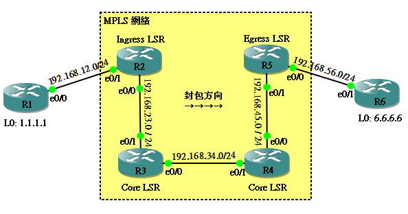
但設定 MPLS 之前,我們要先計劃一下那些 Router 需要執行 MPLS。假設我們希望 R2, R3, R4, R5 使用 MPLS:
然後我們學幾個名詞:
LSR
即 Label Switch Router,即是執行了 MPLS 的 Router,上圖中 R2, R3, R4, R5 都是 LSR。
Ingress LSR
如果按照剛才的例子,封包是由 R1 到 R6 這個方向的話,R2 是封包進入 MPLS 網絡第一個碰到的 Router,稱為 Ingress LSR。Ingress Router 主要是幫進入 MPLS 網絡的封包加上 Label (這個動作也叫作 Push)。
Egress LSR
當封包將要離開 MPLS 網絡時,它經過的最後一個 Router 就是 Egress LSR。Egress LSR 的責任是幫封包移除 Label (也叫作 Pop),讓它離開時重過正常生活。從 R1 到 R6 的方向來說,R5 就是 Egress LSR。
Core LSR
除了 Ingress LSR 和 Egress LSR,其他就是 Core LSR 了。由於 Label 是由每個 Router 自己產生的,所以各 Router 對同一個網絡所使用的 Label 各有不同,因此,封包每經過一隻 Core LSR,都要做一次 Label 轉換的動作 (也叫作 Swap)。
現在我們試試設定這個 MPLS 網絡,所用的指令簡單得你無法相信,就是一個 mpls ip 指令就搞定。
R2(config)#int ethernet 0/0
 R2(config-if)#mpls ip
 R2(config-if)#
R3(config)#interface range ethernet 0/0 - 1
 R3(config-if-range)#mpls ip
 *Mar  1 01:39:17.007: %LDP-5-NBRCHG: LDP Neighbor 192.168.23.2:0 (1) is UP
 R3(config-if-range)#
R4(config)#interface range ethernet 0/0 - 1
 R4(config-if-range)#mpls ip
 *Mar  1 01:40:45.439: %LDP-5-NBRCHG: LDP Neighbor 192.168.34.3:0 (1) is UP
 R4(config-if-range)#
R5(config)#int ethernet 0/1
 R5(config-if)#mpls ip
 *Mar  1 01:42:00.691: %LDP-5-NBRCHG: LDP Neighbor 192.168.45.4:0 (2) is UP
 R5(config-if)#
只要兩隻 Router 的 Interface 都設定好 MPLS,它們就會成為 LDP Neighbor。LDP 是 MPLS 其中一款 Protocol ,如果不做設定,Cisco Router default 使用 LDP,另一款是 TDP,稍後會再說明。剛才說過就算是同一個 Network ,Label 在每一個 Router 上都是不同的,要成為 Neighbor 是因為這些 LSR 需要交換彼此的 Label 資訊。要看到那一個 Label 代表那一個網絡,我們可以用 show mpls forwarding-table ,例如在 R2 的 Label Forwarding Table 可以見到這隻 Router 用 Label 16 來代表 192.168.34.0/24,用 Label 17 來代表 192.168.45.0/24。
R2#show mpls forwarding-table
 Local  Outgoing    Prefix            Bytes tag  Outgoing   Next Hop
 tag    tag or VC   or Tunnel Id      switched   interface
 16     Pop tag     192.168.34.0/24   0          Et0/0      192.168.23.3
 17     16          192.168.45.0/24   0          Et0/0      192.168.23.3
 18     18          192.168.56.0/24   0          Et0/0      192.168.23.3
 19     20          6.6.6.6/32        0          Et0/0      192.168.23.3
 20     Untagged    1.1.1.1/32        0          Et0/1      192.168.12.1
不過,每隻 LSR 的 Label Forwarding Table 是不相同的,你用 Label 17 代表 192.168.45.0/24 不等於我的 Label 17 代表 192.168.45.0/24,看看 R3 便知道:
R3#show mpls forwarding-table
 Local  Outgoing    Prefix            Bytes tag  Outgoing   Next Hop
 tag    tag or VC   or Tunnel Id      switched   interface
 16     Pop tag     192.168.45.0/24   0          Et0/0      192.168.34.4
 17     Pop tag     192.168.12.0/24   0          Et0/1      192.168.23.2
 18     17          192.168.56.0/24   0          Et0/0      192.168.34.4
 19     20          1.1.1.1/32        0          Et0/1      192.168.23.2
 20     20          6.6.6.6/32        0          Et0/0      192.168.34.4
現在介紹一下每一個欄位的意思:
Local tag
剛剛說過,就是 Label 的意思。Label 長度為 20 bits,Label 0 至 15 是保留不用的,所以 16 至 1,048,575 可用。
Outgoing tag or VC
由於每個 LSR 的 Label Forwarding Table 不相同,所以當 Router 收到一個封包然後要傳送出去時,有可能需要更改 Label,稱為 Swap。就以上的例子,當 R2 收到 Label 17 目的地為192.168.45.0 /24 的封包時,因為它知道 R3 的 192.168.45.0/24 是 Label 16 (是 LDP 讓它知道),所以它會把 Label 17 的封包改成 Label 16 才丟出去 Eth 0/0。
如果此欄是 Untagged,意思是會把所有 Label 移除,因為這個 Network 連接著非 MPLS 的 Interface。用 R2 作例子,因為我們知道 1.1.1.1/32 的 Next Hop 是 R1,而連接著 R1 的 Interface 並無執行 MPLS,所以 R2 會把 Label 移除後才丟出去 Eth0/1。
Pop 的意思也是移除 Label,不過只移除最外層的 Label,有時候比較高階的設定,會動用到多層 Label,Pop 就是移除最外層的。在 R2 顯示 192.168.34.0/24 的封包會被 Pop 後才丟給 R3,為什麼呢?因為 R2 知道 R3 正正連接著 192.168.34.0/24,當然 R2 可以把 Label Swap 成一個新的 Label ,然後傳給 R3,再由 R3 查 Label Forwarding Table 後把 Label Pop 掉,最後查 Routing Table 把封包丟出去。但聰明的 R2 選擇預先把 Label Pop 掉,然後傳給 R3,讓它直接查 Routing Table,省了一次查 Label Forwarding Table 的動作,這個聰明的機制叫做 Penultimate Hop Popping (PHP),但這個機制有利有弊,在介紹 explicit-null 時會有更詳細的說明。
Prefix or Tunnel Id
在 IP Network 來說就是 Label 所代表的 Network Prefix。
Byte Tag switched
即是傳送了多少個 Byte,如果數字有累加的話代表傳送成功了。
Outgoing interface
做了 Label 轉換動作後 (Pop, Swap, Untagged 等),應從那個 Interface 丟出去。
Next Hop
明顯就是 Next Hop IP。
MPLS 的設定是很自動化的,我們甚至不能為 Network 設定 Label 的值,LSR default 會使用 16 至 1,048,575 作為 Label 值,但如你因為某些原因想把範圍縮少的話,可以用 mpls label range <min> <max> 這道指令,但必需要 reload 後再生效。
R2(config)#mpls label range 50 100
 % Label range changes will take effect at the next reload.
 R2(config)#exit
 R2#write memory
 R2#reload

 <After Reloaded>

 R2#show mpls forwarding-table
 Local  Outgoing    Prefix            Bytes tag  Outgoing   Next Hop
 tag    tag or VC   or Tunnel Id      switched   interface
 50     Pop tag     192.168.34.0/24   0          Et0/0      192.168.23.3
 51     16          192.168.45.0/24   0          Et0/0      192.168.23.3
 52     18          192.168.56.0/24   0          Et0/0      192.168.23.3
 53     Untagged    1.1.1.1/32        0          Et0/1      192.168.12.1
 54     20          6.6.6.6/32        0          Et0/0      192.168.23.3
要看 MPLS 把 Label 轉換的過程,可以用 debug mpls packets 這道指令,我們用 R3 作示範:
R3#debug mpls packets
 MPLS packet debugging is on
首先用 R1 的 1.1.1.1 Ping R6 的 6.6.6.6:
R1#ping 6.6.6.6 source 1.1.1.1

 Type escape sequence to abort.
 Sending 5, 100-byte ICMP Echos to 6.6.6.6, timeout is 2 seconds:
 Packet sent with a source address of 1.1.1.1
 !!!!!
 Success rate is 100 percent (5/5), round-trip min/avg/max = 200/251/316 ms
 R1#
R3 便會收到從 R2 來的封包 (recvd),Label 是 20,根據 R3 的 Label Forwarding Table,Label 2 會 Swap 成 Label 17,然後送出去 (xmit)。
R3#show mpls forwarding-table
 Local  Outgoing    Prefix            Bytes tag  Outgoing   Next Hop
 tag    tag or VC   or Tunnel Id      switched   interface
 16     Pop tag     192.168.12.0/24   1140       Et0/1      192.168.23.2
 17     Pop tag     192.168.45.0/24   1140       Et0/0      192.168.34.4
 18     16          192.168.56.0/24   0          Et0/0      192.168.34.4
 19     19          1.1.1.1/32        1180       Et0/1      192.168.23.2
 20     17          6.6.6.6/32        1180       Et0/0      192.168.34.4
 R3#
 *Mar  1 00:14:39.455: MPLS: Et0/1: recvd: CoS=0, TTL=254, Label(s)=20
 *Mar  1 00:14:39.459: MPLS: Et0/0: xmit: CoS=0, TTL=253, Label(s)=17

 <Output Omitted>
如果 R1 Ping 的是 192.168.45.0/24,封包離開 R3 時就會被 Pop 掉 (no label)。
R1#ping 192.168.45.4 source 192.168.12.1

 Type escape sequence to abort.
 Sending 5, 100-byte ICMP Echos to 192.168.45.4, timeout is 2 seconds:
 Packet sent with a source address of 192.168.12.1
 !!!!!
 Success rate is 100 percent (5/5), round-trip min/avg/max = 136/162/204 ms
 R1#
R3#
 *Mar  1 00:19:05.859: MPLS: Et0/1: recvd: CoS=0, TTL=254, Label(s)=17
 *Mar  1 00:19:05.863: MPLS: Et0/0: xmit: (no label)
TDP 與 LDP
剛才有提及過 TDP 與 LDP,其實兩種都是 MPLS 的 Protocol。TDP (Tag Distribution Protocol) 是 Cisco 獨家的,是較早期的 MPLS Protocol。後來 IETF 制訂了 LDP (Label Distribution Protocol),現在比較常用,Cisco Router 現在也 default 使用 LDP 了。除非有很特殊的情況 (例如 Cisco 考試……),否則一般都不會刻意使用 TDP 了。
如果想使用 TDP,可以用一個 global 指令 mpls label protocol tdp,這樣所有 Interface 都會轉用 TDP。這個指令在 Interface 下也可用,變成只有該 Interface 執行 TDP。要知道 Interface 究竟在使用那一種 MPLS Protocol,可以使用 show mpls interfaces。
R3#show mpls interfaces
 Interface              IP            Tunnel   Operational
 Ethernet0/0            Yes (ldp)     No       Yes
 Ethernet0/1            Yes (tdp)     No       Yes
Implicit null 與 Explicit null
還記得剛才曾經提及過 Penultimate Hop Popping (PHP) 嗎?用 PHP 需然可以讓 Last Hop 的工作量減少,但會產生一個問題。32 bits Label 當中,除了一個 20 bits 的 Label 值之外,還包含了一些 QoS 資訊,Last Hop 可能需要利用這些資訊來對封包進行 QoS 的判斷,如果太早 Pop 走 Label ,Last Hop 就無法得到 QoS 資訊。
所謂 PHP,其實是 LSR default 使用了 Implicit null,如果想保留 Label 至 Last Hop,可以使用mpls ldp explicit-null。請先看看 R4 的 Label Forwarding Table,Label 16 來到 R4 應該是被 Pop 然後經 Eth0/0 送到 R5 的,因為 R4 知道 192.168.56.0/24 是直接連著 R5 的。為了求證,在 R4 開 debug mpls packets 用 R1 Ping 192.168.56.6,在 R4 可以確認 Lable 被 Pop。
R4#show mpls forwarding-table
 Local  Outgoing    Prefix            Bytes tag  Outgoing   Next Hop
 tag    tag or VC   or Tunnel Id      switched   interface
 16     Pop tag     192.168.56.0/24   0          Et0/0      192.168.45.5
 17     16          6.6.6.6/32        0          Et0/0      192.168.45.5
 18     Pop tag     192.168.23.0/24   0          Et0/1      192.168.34.3
 19     16          192.168.12.0/24   0          Et0/1      192.168.34.3
 20     19          1.1.1.1/32        0          Et0/1      192.168.34.3
R4#debug mpls packets
 MPLS packet debugging is on
 R4#
 *Mar  1 00:09:13.827: MPLS: Et0/1: recvd: CoS=0, TTL=253, Label(s)=16
 *Mar  1 00:09:13.827: MPLS: Et0/0: xmit: (no label)
現在,我們希望 R4 保留 Label 傳給 R5,所以在 R5 下指令 mpls ldp explicit-null ,作用是告訴 Penultimate Hop:「就算我是 Last Hop,請保留 Label 給我!」 然後在 R4 看看 Label Forwarding Table,這時候會發現 Outgoing tag 變成 0 了,而不是 Pop。
R5(config)#mpls ldp explicit-null
R4#show mpls forwarding-table
 Local  Outgoing    Prefix            Bytes tag  Outgoing   Next Hop
 tag    tag or VC   or Tunnel Id      switched   interface
 16     0           192.168.56.0/24   0          Et0/0      192.168.45.5
 17     16          6.6.6.6/32        0          Et0/0      192.168.45.5
 18     Pop tag     192.168.23.0/24   0          Et0/1      192.168.34.3
 19     16          192.168.12.0/24   590        Et0/1      192.168.34.3
 20     19          1.1.1.1/32        0          Et0/1      192.168.34.3
在 R1 Ping 192.168.56.6,證實 R4 傳給 R5 的封包會 Swap 成 Label 0,Label 被成功保留了。
R4#
 *Mar  1 00:17:07.879: MPLS: Et0/1: recvd: CoS=0, TTL=253, Label(s)=16
 *Mar  1 00:17:07.883: MPLS: Et0/0: xmit: CoS=0, TTL=252, Label(s)=0
VRF-lite
接下來話題轉一轉,我們來介紹一下 VRF (Virtual Routing and Fowarding)。VRF 經常與 MPLS 一起使用來實行 MPLS-VPN,但在 MPLS-VPN 教學之前,我們可以先學會簡化版,即是 VRF-lite。VRF 可以解釋為 「Layer 3 的 VLAN」 技術,VLAN 把一個 LAN 分成很多個 Virtual 的 LAN,而 VRF 能夠把一個 Routing Table 分成很多個 Virtual 的 Routing Table 。什麽時候會使用到 VRF-lite 呢?假如你是一間 ISP 的 administrator,這間 ISP 有兩位客人都同時跟你的 Router 執行 OSPF Routing Protocol,不幸地,他們都使用相同 subnet 的 IP address,難道你要叫他們其中一位更改 IP subnet 嗎?當然不行,這時候 VRF 便大派用場了。請看以下例子。
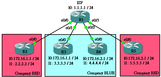
上圖中 Company RED 與 Company BLUE 都希望使用 172.16.1.0/24 及 172.16.2.0/24 這兩個 Network。所以 ISP 的 R1 要動點手腳,首先要用 ip vrf <name> 去設定 VRF。
R1(config)#ip vrf RED
R1(config-vrf)#exit
R1(config)#ip vrf BLUE
R1(config-vrf)#exit
夠簡單吧!然後把 Interface e0/0 設定成適當的 VRF,在 Interface 使用 ip vrf forwarding <name> 指令便可,不過每次 VRF 有改動之後系統會自動把 IP 移除,因此必需重新輸入一次 IP。用同樣的方法把 E0/1 和 E0/2 放進 VRF BLUE,E0/3 放進 VRF RED。
R1(config)#interface ethernet 0/0
R1(config-if)#ip vrf forwarding RED
% Interface Ethernet0/0 IP address 192.168.12.1 removed due to enabling VRF RED
R1(config-if)#ip address 192.168.12.1 255.255.255.0
完成後可使用 show ip vrf interface 查證:
R1#show ip vrf interfaces
Interface              IP-Address      VRF                              Protocol
Et0/0                  192.168.12.1    RED                               up
Et0/1                  192.168.13.1    BLUE                              up
Et0/2                  192.168.14.1    BLUE                              up
Et0/3                  192.168.15.1    RED                               up
最後,就執行 OSPF,但要在 Process ID 後補上 VRF 的名。
R1(config)#router ospf 1 vrf RED
 R1(config-router)#network 0.0.0.0 255.255.255.255 area 0
 R1(config)#router ospf 2 vrf BLUE
 R1(config-router)#network 0.0.0.0 255.255.255.255 area 0
而 R2 至 R5,即是客戶的 Router 不用執行任何關於 VRF 的指令,只需要照常執行 OSPF 便可以了。
R2(config)#router ospf 1
 R2(config-router)#network 0.0.0.0 255.255.255.255 area 0
待 Route Update 好之後,在 R2 能夠到達 R5,R3 能夠到達 R4。
R2#show ip route | begin Gateway
 Gateway of last resort is not set

 C    192.168.12.0/24 is directly connected, Ethernet0/0
      2.0.0.0/24 is subnetted, 1 subnets
 C       2.2.2.0 is directly connected, Loopback1
 O    192.168.15.0/24 [110/20] via 192.168.12.1, 00:03:21, Ethernet0/0
      5.0.0.0/32 is subnetted, 1 subnets
 O       5.5.5.5 [110/21] via 192.168.12.1, 00:03:21, Ethernet0/0
      172.16.0.0/16 is variably subnetted, 2 subnets, 2 masks
 C       172.16.1.0/24 is directly connected, Loopback0
 O       172.16.2.1/32 [110/21] via 192.168.12.1, 00:03:21, Ethernet0/0
 R2#ping 172.16.2.1 source 172.16.1.1

 Type escape sequence to abort.
 Sending 5, 100-byte ICMP Echos to 172.16.2.1, timeout is 2 seconds:
 !!!!!

 Success rate is 100 percent (5/5), round-trip min/avg/max = 52/76/96 ms
R3#show ip route | begin Gateway
 Gateway of last resort is not set

 C    192.168.13.0/24 is directly connected, Ethernet0/0
 O    192.168.14.0/24 [110/20] via 192.168.13.1, 00:04:24, Ethernet0/0
      3.0.0.0/24 is subnetted, 1 subnets
 C       3.3.3.0 is directly connected, Loopback1
      4.0.0.0/32 is subnetted, 1 subnets
 O       4.4.4.4 [110/21] via 192.168.13.1, 00:04:24, Ethernet0/0
      172.16.0.0/16 is variably subnetted, 2 subnets, 2 masks
 C       172.16.1.0/24 is directly connected, Loopback0
 O       172.16.2.1/32 [110/21] via 192.168.13.1, 00:04:24, Ethernet0/0
 R3#ping 172.16.2.1 source 172.16.1.1

 Type escape sequence to abort.
 Sending 5, 100-byte ICMP Echos to 172.16.2.1, timeout is 2 seconds:
 !!!!!

 Success rate is 100 percent (5/5), round-trip min/avg/max = 76/99/128 ms
最精彩是 R1 現在有 3 個 Routing Table,分別是 1) 基本的 2) VRF RED 及 3) VRF BLUE,我們可以用 show ip route vrf <name> 來查看 VRF 的 Routing Table。
R1#show ip route | begin Gateway
 Gateway of last resort is not set

      1.0.0.0/32 is subnetted, 1 subnets
 C       1.1.1.1 is directly connected, Loopback0
 R1#
 R1#show ip route vrf RED | begin Gateway
 Gateway of last resort is not set

 C    192.168.12.0/24 is directly connected, Ethernet0/0
      2.0.0.0/32 is subnetted, 1 subnets
 O       2.2.2.2 [110/11] via 192.168.12.2, 00:04:55, Ethernet0/0
 C    192.168.15.0/24 is directly connected, Ethernet0/3
      5.0.0.0/32 is subnetted, 1 subnets
 O       5.5.5.5 [110/11] via 192.168.15.5, 00:04:55, Ethernet0/3
      172.16.0.0/32 is subnetted, 2 subnets
 O       172.16.1.1 [110/11] via 192.168.12.2, 00:04:55, Ethernet0/0
 O       172.16.2.1 [110/11] via 192.168.15.5, 00:04:55, Ethernet0/3
 R1#
 R1#show ip route vrf BLUE | begin Gateway
 Gateway of last resort is not set

 C    192.168.13.0/24 is directly connected, Ethernet0/1
 C    192.168.14.0/24 is directly connected, Ethernet0/2
      3.0.0.0/32 is subnetted, 1 subnets
 O       3.3.3.3 [110/11] via 192.168.13.3, 00:05:13, Ethernet0/1
      4.0.0.0/32 is subnetted, 1 subnets
 O       4.4.4.4 [110/11] via 192.168.14.4, 00:05:13, Ethernet0/2
      172.16.0.0/32 is subnetted, 2 subnets
 O       172.16.1.1 [110/11] via 192.168.13.3, 00:05:13, Ethernet0/1
 O       172.16.2.1 [110/11] via 192.168.14.4, 00:05:13, Ethernet0/2
不算太難吧!無錯,OSPF 在 VRF 的設定上比較簡單,不過 RIP 和 EIGRP 的設定上就稍有不同。現在請先把所有 Router 的 OSPF 設定刪除,我們現在試試在 VRF RED 執行 RIP 讓 R2 和 R5 連接。
要在 RIP 使用 VRF,需要在 RIP 設定中使用 address-family 指令,你可以把它想像成 VRF RED 是 RIP 設定下面的其中一個 Sub Group。
R1(config)#router rip
 R1(config-router)#address-family ipv4 vrf RED
 R1(config-router-af)#network 192.168.12.0
 R1(config-router-af)#network 192.168.15.0
 R1(config-router-af)#version 2
 R1(config-router-af)#no auto-summary
 R1(config-router-af)#exit-address-family
 R1(config-router)#
至於 R2 和 R5 只要按照 RIP 的基本設定便可以,下面只顯示 R2 的設定:
R2(config)#router rip
 R2(config-router)#network 192.168.12.0
 R2(config-router)#network 172.16.0.0
 R2(config-router)#network 2.0.0.0
 R2(config-router)#version 2
 R2(config-router)#no auto-summary
跟著試試把 R3 和 R4 用 EIGRP。EIGRP 又要怎樣玩呢?其實也是用 address-family。不過有一點要注意的是 autonomous (AS) number,由於 address-family 是 EIGRP 裡的一個 Sub Group,你必需為它設定一個 AS number,而 R3 和 R4 要與 R1 的 VRF 成為 EIGRP Neighbor,用的 AS number 也是 address-family 裡面那個,看一看以下例子就會明白。
R1(config)#router eigrp 1
 R1(config-router)#address-family ipv4 vrf BLUE
 R1(config-router-af)#autonomous-system 10
 R1(config-router-af)#network 192.168.13.0 0.0.0.255
 R1(config-router-af)#network 192.168.14.0 0.0.0.255
 R1(config-router-af)#no auto-summary
 R1(config-router-af)#exit-address-family
除了 Network IP 之外,R3 與 R4 設定基本相同。
R3(config)#router eigrp 10
 R3(config-router)#network 192.168.13.0 0.0.0.255
 R3(config-router)#network 172.16.1.0 0.0.0.255
 R3(config-router)#network 3.3.3.0 0.0.0.255
 R1(config-router)#no auto-summary
完成設定後看 R1 vrf Routing Table,可見 RED 在玩 RIP,而 BLUE 在玩 EIGRP。
R1#show ip route vrf RED | begin Gateway
 Gateway of last resort is not set

 C    192.168.12.0/24 is directly connected, Ethernet0/0
      2.0.0.0/24 is subnetted, 1 subnets
 R       2.2.2.0 [120/1] via 192.168.12.2, 00:00:21, Ethernet0/0
 C    192.168.15.0/24 is directly connected, Ethernet0/3
      5.0.0.0/24 is subnetted, 1 subnets
 R       5.5.5.0 [120/1] via 192.168.15.5, 00:00:26, Ethernet0/3
      172.16.0.0/24 is subnetted, 2 subnets
 R       172.16.1.0 [120/1] via 192.168.12.2, 00:00:21, Ethernet0/0
 R       172.16.2.0 [120/1] via 192.168.15.5, 00:00:26, Ethernet0/3
 R1#
 R1#show ip route vrf BLUE | begin Gateway
 Gateway of last resort is not set

 C    192.168.13.0/24 is directly connected, Ethernet0/1
 C    192.168.14.0/24 is directly connected, Ethernet0/2
      3.0.0.0/24 is subnetted, 1 subnets
 D       3.3.3.0 [90/409600] via 192.168.13.3, 00:00:32, Ethernet0/1
      4.0.0.0/24 is subnetted, 1 subnets
 D       4.4.4.0 [90/409600] via 192.168.14.4, 00:00:32, Ethernet0/2
      172.16.0.0/24 is subnetted, 2 subnets
 D       172.16.1.0 [90/409600] via 192.168.13.3, 00:00:32, Ethernet0/1
 D       172.16.2.0 [90/409600] via 192.168.14.4, 00:00:32, Ethernet0/2
MPLS VPN
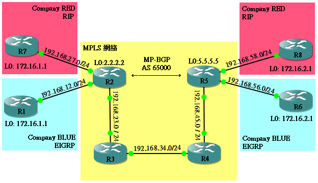
雖然 VRF-lite 可以解決不同客戶有相同 IP 的問題,不過,世事多變!如果今次你遇到下圖中這個網絡,客戶 A 與 客戶 B 分別連接著 ISP MPLS 網絡中的不同 Router,我們又如何把客戶的網絡接通?這是就要出動真正的 MPLS VPN,加上 MP-BGP 技術,再加上之前所提到的 VRF 才能搞定。讀者請先有心理準備,這會是一個頗難的課題。
MP-BGP
首先假設 MPLS 網絡的部份已經設定好,跟著我們需要把 R2 和 R5 用 MP-BGP (Multiprotocol-BGP) 連接起來。平時所使用的 BGP,一般都是用在 IPv4 的路由交換。其實 BGP 除了作 IPv4 路由交換之外,還可以設定成 VPN ,用作交換 VRF 的路由。至於設定的方法在下面會有說明。
Route Distinguisher
另外,我們要知道什麼是 RD (Route Distinguisher) ,由於 RED 和 BLUE 公司都有相同的網絡,假設 R2 幫我們把路由發到 R5,但 R5 又怎樣分辨那條是 RED 的 172.16.1.0/24,那條是 BLUE 的 172.16.1.0/24 呢?所以,我們要在發出去的 Route 中加點東西作分辨,這就是 RD 的用途。RD 是一個 96 bits 的值,格式通常是 <AS number>:<任意number> 或 <IP>:<任意number>,例如:65000:100 或 172.16.1.0:200。RD 會加在 IP 之前,這樣 Router 就可以靠這個 RD 來區分不同來源的 Route。
Route Target
還有還有,我們還要學 RT (Route Target)。套用剛才的例子,R2 把兩間公司的 Route 好好的加了 RD,但其實它是可以選擇是不是要把這些 Route 發出來,而另一方面 R5 也可以選擇要接收那些 Route,這就是 RT 的作用。RT 是一個 64 bits 的值,是 BGP 的 Extended Community (當是一個特別的欄位好了) ,你可以為某個 VRF 的 Route 標好了 RT 然後發出去,也可選擇只接收那個 RT 的 Route。現階段可能還是比較難理解,但相信我,一路看下去就會更加明白。
R5#show ip bgp vpnv4 all 172.16.1.1
 BGP routing table entry for 65000:100:172.16.1.0/24, version 4
 Paths: (1 available, best #1, table RED)
   Not advertised to any peer
   Local
     2.2.2.2 (metric 31) from 2.2.2.2 (2.2.2.2)
       Origin incomplete, metric 1, localpref 100, valid, internal, best
       Extended Community: RT:100:100
       mpls labels in/out nolabel/21
好!現在我們嘗試為上面的網絡配置 MPLS VPN,過程相當煩複,不要緊,我們一步一步做下去。假設黃色部份 ISP 的網絡已經配置好 OSPF,並且執行了 MPLS。
步驟 1:設置 VRF
跟 VRF-lite 一樣是用 ip vrf <name> 指令,但不同的是我們要為 VRF 設 RD 和 RT。
rd <num>:<num> 設定 RD
route-target export <num>:<num> 設定 RT,export 表示這個 VRF 的 Route 會用 100:100 發送出去,import 即是這個 VRF 會接收 100:100 的 Route,如果 import 和 export 的 RT 相同,乾脆用 both 便可以了。
R2(config)#ip vrf RED
 R2(config-vrf)#rd 65000:100
 R2(config-vrf)#route-target export 100:100
 R2(config-vrf)#route-target import 100:100
 R2(config-vrf)#ip vrf BLUE
 R2(config-vrf)#rd 65000:200
 R2(config-vrf)#route-target both 200:200
R5(config)#ip vrf RED
 R5(config-vrf)#rd 65000:100
 R5(config-vrf)#route-target both 100:100
 R5(config-vrf)#ip vrf BLUE
 R5(config-vrf)#rd 65000:200
 R5(config-vrf)#route-target both 200:200
然後把 VRF 放置於適當的 Interface,設定方法之前說過,在此不詳述,只顯示結果:
R2#show ip vrf interfaces
 Interface              IP-Address      VRF                              Protocol
 Et0/1                  192.168.12.2    BLUE                             up
 Et0/2                  192.168.27.2    RED                              up
R5#show ip vrf interfaces
 Interface              IP-Address      VRF                              Protocol
 Et0/0                  192.168.56.5    BLUE                             up
 Et0/2                  192.168.58.5    RED
步驟 2:設置 MP-BGP
剛才說過我們要把 R2 和 R5 設定 MP-BGP,首先建好基本的 BGP Neighbor:
hostname R2
 !
 router bgp 65000
  no synchronization
  neighbor 5.5.5.5 remote-as 65000
  neighbor 5.5.5.5 update-source Loopback0
  no auto-summary
hostname R5
 !
 router bgp 65000
  no synchronization
  neighbor 2.2.2.2 remote-as 65000
  neighbor 2.2.2.2 update-source Loopback0
  no auto-summary
然後用 address-family vpnv4 進入 address family mode 進行設定:
neighbor <IP> activate 是告知使用那個 neighbor IP 來進行 vpnv4
neighbor <IP> send-community 是告訴這個 vpnv4 需要傳送 community (即是剛剛說的 RT 就是其中一種 community 啦)
R2(config)#router bgp 65000
 R2(config-router)#address-family vpnv4
 R2(config-router-af)#neighbor 5.5.5.5 activate
 R2(config-router-af)#neighbor 5.5.5.5 send-community
 R2(config-router-af)#exit-address-family
R5(config)#router bgp 65000
 R5(config-router)#address-family vpnv4
 R5(config-router-af)#neighbor 2.2.2.2 activate
 R5(config-router-af)#neighbor 2.2.2.2 send-community
 R5(config-router-af)#exit-address-family
步驟 3:RED 的 RIP 設定
然後我們幫 RED 公司設定 RIP,此部份在 VRF-lite 已說明過,在此不加以詳述。以下為 R2 和 R7 的 RIP 設定:
hostname R2
 !
 router rip
  !
  address-family ipv4 vrf RED
   network 192.168.27.0
   no auto-summary
   version 2
  exit-address-family
hostname R7
 !
 router rip
  version 2
  network 172.16.0.0
  network 192.168.27.0
  no auto-summary
以下是 R5 和 R8 的 RIP 設定:
hostname R5
 !
 router rip
  !
  address-family ipv4 vrf RED
   network 192.168.58.0
   no auto-summary
   version 2
  exit-address-family
hostname R8
 !
 router rip
  version 2
  network 172.16.0.0
  network 192.168.58.0
  no auto-summary
所以 R2 和 R5 都收到從 RIP 傳來的 Route 了。
R2#show ip route vrf RED | begin Gateway
 Gateway of last resort is not set

 C    192.168.27.0/24 is directly connected, Ethernet0/2
      172.16.0.0/24 is subnetted, 1 subnets
 R       172.16.1.0 [120/1] via 192.168.27.7, 00:00:20, Ethernet0/2
R5#show ip route vrf RED | begin Gateway
 Gateway of last resort is not set

 C    192.168.58.0/24 is directly connected, Ethernet0/2
      172.16.0.0/24 is subnetted, 1 subnets
 R       172.16.2.0 [120/1] via 192.168.58.8, 00:00:03, Ethernet0/2
步驟 4:BLUE 的 EIGRP 設定
然後我們幫 BLUE 公司設定 EIGRP,此部份也在 VRF-lite 已說明過,在此不加以詳述。以下為 R1 和 R2 的 EIGRP 設定:
R2(config)#router eigrp 1
 R2(config-router)#address-family ipv4 vrf BLUE
 R2(config-router-af)#autonomous-system 20
 R2(config-router-af)#network 192.168.12.0 0.0.0.255
 R2(config-router-af)#no auto-summary
R1(config)#router eigrp 20
 R1(config-router)#network 192.168.12.0 0.0.0.255
 R1(config-router)#network 172.16.1.0 0.0.0.255
 R1(config-router)#no auto-summary
以下為 R5 和 R6 的 EIGRP 設定:
R5(config)#router eigrp 1
 R5(config-router)#address-family ipv4 vrf BLUE
 R5(config-router-af)#autonomous-system 20
 R5(config-router-af)#network 192.168.56.0 0.0.0.255
 R5(config-router-af)#no auto-summary
R6(config)#router eigrp 20
 R6(config-router)#network 192.168.56.0 0.0.0.255
 R6(config-router)#network 172.16.2.0 0.0.0.255
 R6(config-router)#no auto-summary
如果設定無問題,在 R2 和 R5 會見到由 EIGRP 發過來的 Router。
R2#show ip route vrf BLUE | begin Gateway
 Gateway of last resort is not set

 C    192.168.12.0/24 is directly connected, Ethernet0/1
      172.16.0.0/24 is subnetted, 1 subnets
 D       172.16.1.0 [90/409600] via 192.168.12.1, 00:06:35, Ethernet0/1
R5#show ip route vrf BLUE | begin Gateway
 Gateway of last resort is not set

      172.16.0.0/24 is subnetted, 1 subnets
 D       172.16.2.0 [90/409600] via 192.168.56.6, 00:02:15, Ethernet0/0
 C    192.168.56.0/24 is directly connected, Ethernet0/0
步驟 5:Redistribute
現在怎樣把分隔兩地的 Route 好好的帶到對岸呢?答案就是依靠我們剛剛建立的 MP-BGP 這道橋樑。先用 RIP 作例子,我們要把 RIP 的 Route Redistribute 到 BGP 裡,乘坐 BGP 去到對岸後,又再把 BGP redistribute 回到 RIP。不過要留意的是,RIP 是屬於 VRF RED 的,所以要乘屬於 VRF RED 的 BGP,要對號入座喔!
來試試看,在 R2 的 BGP 建立 VRF RED 然後 redistribute RIP,完成後用 show ip bgp vpnv4 vrf RED 已經可以看到 RIP 的 route 進入 BGP VRF RED 的 Database 了!
R2(config)#router bgp 65000
 R2(config-router)#address-family ipv4 vrf RED
 R2(config-router-af)#redistribute rip
 R2(config-router-af)#exit-address-family
 R2(config-router-af)#end
 R2#
 R2#show ip bgp vpnv4 vrf RED
 BGP table version is 5, local router ID is 2.2.2.2
 Status codes: s suppressed, d damped, h history, * valid, > best, i - internal,
               r RIB-failure, S Stale
 Origin codes: i - IGP, e - EGP, ? - incomplete

    Network          Next Hop            Metric LocPrf Weight Path
 Route Distinguisher: 65000:100 (default for vrf RED)
 *> 172.16.1.0/24    192.168.27.7             1         32768 ?
 *> 192.168.27.0     0.0.0.0                  0         32768 ?
來到 R5 又看看有沒有收到 RIP 這批乘客:
R5#show ip bgp vpnv4 vrf RED
 BGP table version is 23, local router ID is 5.5.5.5
 Status codes: s suppressed, d damped, h history, * valid, > best, i - internal,
               r RIB-failure, S Stale
 Origin codes: i - IGP, e - EGP, ? - incomplete

    Network          Next Hop            Metric LocPrf Weight Path
 Route Distinguisher: 65000:100 (default for vrf RED)
 *>i172.16.1.0/24    2.2.2.2                  1    100      0 ?
 *>i192.168.27.0     2.2.2.2                  0    100      0 ?
有了!現在我們要做的是把 BGP 的乘客 redistribute 回到 RIP:
R5(config)#router rip
 R5(config-router)#address-family ipv4 vrf RED
 R5(config-router-af)#redistribute bgp 65000 metric 1
 R5(config-router-af)#exit-address-family
最後看看 R8 的 Routing Table 吧,收到從對岸遠渡而來的 Route 了。
R8#show ip route | begin Gateway
 Gateway of last resort is not set

 C    192.168.58.0/24 is directly connected, Ethernet0/0
 R    192.168.27.0/24 [120/1] via 192.168.58.5, 00:00:12, Ethernet0/0
      172.16.0.0/24 is subnetted, 2 subnets
 R       172.16.1.0 [120/1] via 192.168.58.5, 00:00:12, Ethernet0/0
 C       172.16.2.0 is directly connected, Loopback0
然後我們把同一個設定倒轉再做一遍,把 R5 的 RIP route 經 BGP 送到 R2:
R5(config)#router bgp 65000
 R5(config-router)#address-family ipv4 vrf RED
 R5(config-router-af)#redistribute rip
 R5(config-router-af)#exit-address-family
 R5(config-router-af)#end
R2(config)#router rip
 R2(config-router)#address-family ipv4 vrf RED
 R2(config-router-af)#redistribute bgp 65000 metric 1
 R2(config-router-af)#exit-address-family
R7 收到從 R8 來的 RIP Route,而且……而且還 PING 通了!!
R7#show ip route | begin Gateway
 Gateway of last resort is not set

 R    192.168.58.0/24 [120/1] via 192.168.27.2, 00:00:16, Ethernet0/0
 C    192.168.27.0/24 is directly connected, Ethernet0/0
      172.16.0.0/24 is subnetted, 2 subnets
 C       172.16.1.0 is directly connected, Loopback0
 R       172.16.2.0 [120/1] via 192.168.27.2, 00:00:16, Ethernet0/0
 R7#
 R7#ping 172.16.2.1 source 172.16.1.1

 Type escape sequence to abort.
 Sending 5, 100-byte ICMP Echos to 172.16.2.1, timeout is 2 seconds:
 !!!!!
 Success rate is 100 percent (5/5), round-trip min/avg/max = 200/268/336 ms
完成了 RIP 的部份,我們再來試試 EIGRP 這一邊,其實做法相同。以下顯示了 R2 的設定,而 R5 的設定則和 R2 相同。
R2(config)#router bgp 65000
 R2(config-router)#address-family ipv4 vrf BLUE
 R2(config-router-af)#redistribute eigrp 20
 R2(config-router-af)#exit-address-family
 R2(config-router)#exit
 R2(config)#router eigrp 1
 R2(config-router)#address-family ipv4 vrf BLUE
 R2(config-router-af)#redistribute bgp 65000 metric 1 0 0 1 1
 R2(config-router-af)#exit-address-family
R1 有收到 EIGRP Route,也能夠 Ping 到對面。
R1#show ip route | begin Gateway
 Gateway of last resort is not set

 C    192.168.12.0/24 is directly connected, Ethernet0/0
      172.16.0.0/24 is subnetted, 2 subnets
 C       172.16.1.0 is directly connected, Loopback0
 D       172.16.2.0 [90/435200] via 192.168.12.2, 00:07:21, Ethernet0/0
 D    192.168.56.0/24 [90/307200] via 192.168.12.2, 00:07:21, Ethernet0/0
 R1#
 R1#ping 172.16.2.1 source 172.16.1.1

 Type escape sequence to abort.
 Sending 5, 100-byte ICMP Echos to 172.16.2.1, timeout is 2 seconds:
 !!!!!
 Success rate is 100 percent (5/5), round-trip min/avg/max = 300/386/448 ms
小結
就是這樣,終於讓兩家公司各自 PING 到自己的對家,可謂功德圓滿。這確是個難度頗高的設定,筆者自己也花了很多時間去學習。不知大家有沒有留意到,這個 MPLS VPN 最美妙的地方,其實是在於 R3 和 R4 這兩隻 Router 的 Route Table 中,一直都沒有 RED 公司和 BLUE 公司的 Route,它們對 RED 公司和 BLUE 公司的 Route 其實是一無所知的,只是在忠實地執行 Label Switching,就算你有一百家公司在外面,他們都沒有為那些 Route 操心過,這也是 MPLS 其中一個想達到的目的之一。
Coming Soon……
sham link
相關主題
Jan Ho 2014-02-09
Posted In: menu-tall-2-zh-hant, 虛擬私人網路 VPN
發佈留言