目錄
前言
Spanning Tree 的終極一課,就是 Multiple Spanning Tree Protocol (MSTP)。從傳統 STP 至 RSTP,是速度的進化。而從 RSTP 至 MSTP 則是節省硬件資源和層級式管理的進化。MSTP (又名 802.1s) 繼承了 RSTP 的 Synchronization Process 來達成高效率的收斂 (Convergence),而比 RSTP 優秀的是,MSTP 可把多個 Spanning Tree 分配給不同的 Instance 去減少整個 Spanning Tree 系統的 Topology 數量,本篇假設讀者已深入了解 STP 與 RSTP 原理。
RSTP 現存問題
消耗硬體資源
Cisco 所支緩的 RSTP (或 STP) 都是 Per-VLAN Base 的,即是說 Spanning Tree Topology 數目等於 VLAN 數目。如果 Switch 有 100 個 VLAN 就要處理 100 個 Spanning Tree Topology,包括發送、接收和運算 BPDU,VLAN 越多,對整個網絡所有 Switch 的 CPU 和 RAM 資源都會造成壓力。
MSTP 提出了 Instance 的想法,把多個 VLAN 分組成為不同的 Instance,同一組 Instance 的 VLAN 共用一組 Spanning Tree Topology。舉例:VLAN101 至 VLAN200 共 100 組 VLAN,可把 VLAN101 至 VLAN150 編入 Instance 1,餘下的 VLAN151 至 VLAN200 編入 Instance 2。Spanning Tree Topology 數量由 100 個大大縮減至 2 個。
缺乏區域管理
RSTP 缺乏區域概念,難於管理。MSTP 可把整個網絡分區 (Region) 管理,Region 與 Region 之間不會互相干擾 Topology。每個 Region 會構成一隻巨大的虛擬 Switch (Virtual Switch),每個 Virtual Switch 之間會進行一個獨立的 Spanning Tree 運算,而這個稱為 Common and Internal Spanning Tree (CIST) 又不會影響 Region 裡的 Topology,聽起來相當複雜,在之後的部份將會深入說明。
區域 Region
同一 Region 裡的 Switch 只會處理相同 Region 裡的 BPDU 資訊,從而計算出 Topology。要判斷是否身處在同一個 Region,Switch 會比較 spanning-tree mst configuration 中的 3 個參數。3 個參數均相同才算是同一個 Region。
Configuration Name
Configuration 的名稱,用指令 name 去設定。
Revision Number
設定的版本編號,習慣上每次更改 mst 設定都應把 Revision number 加 1。設定指令為 revision 。
VLAN 及 Instance 對應表
設定 Instance 所包含的 VLAN,指令為 instance <num> vlan <num> 。留意 Cisco Switch 的 MSTP 預設 instance 0 用作 CIST,不可用作 Region 用途。
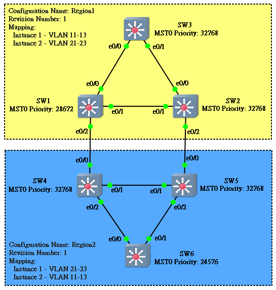
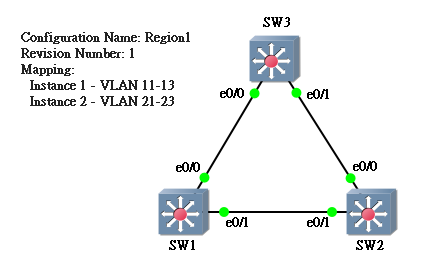
現在試為以下網絡設定 MSTP。

首先在每一隻 Switch 都使用 spanning-tree mst configuration 進入 MST 設定,然後輸入這 3 項必要的參數。
SW1(config)#spanning-tree mst
SW1(config)#spanning-tree mst configuration
SW1(config-mst)#name Region1
SW1(config-mst)#revision 1
SW1(config-mst)#instance 1 vlan 11-13
SW1(config-mst)#instance 2 vlan 21-23
SW2(config)#spanning-tree mst
SW2(config)#spanning-tree mst configuration
SW2(config-mst)#name Region1
SW2(config-mst)#revision 1
SW2(config-mst)#instance 1 vlan 11-13
SW2(config-mst)#instance 2 vlan 21-23
SW3(config)#spanning-tree mst
SW3(config)#spanning-tree mst configuration
SW3(config-mst)#name Region1
SW3(config-mst)#revision 1
SW3(config-mst)#instance 1 vlan 11-13
SW3(config-mst)#instance 2 vlan 21-23
然後可以用 show spanning-tree mst configuration 指令去檢查一下。3 隻 Switch 的結果應該是一模一樣的。留意 MSTP 會把其餘的 VLAN 放進 Instance 0。
SW1#show spanning-tree mst configuration
Name      [Region1]
Revision  1     Instances configured 3

Instance  Vlans mapped
--------  ---------------------------------------------------------------------
0         1-10,14-20,24-4094
1         11-13
2         21-23
-------------------------------------------------------------------------------
SW2#show spanning-tree mst configuration
Name      [Region1]
Revision  1     Instances configured 3

Instance  Vlans mapped
--------  ---------------------------------------------------------------------
0         1-10,14-20,24-4094
1         11-13
2         21-23
-------------------------------------------------------------------------------
SW3#show spanning-tree mst configuration
Name      [Region1]
Revision  1     Instances configured 3

Instance  Vlans mapped
--------  ---------------------------------------------------------------------
0         1-10,14-20,24-4094
1         11-13
2         21-23
-------------------------------------------------------------------------------
確定無誤後在每隻 Switch 輸入指令 spanning-tree mode mst,這樣子 Region1 就建立起來了。
SW1(config)#spanning-tree mode mst
SW2(config)#spanning-tree mode mst
SW3(config)#spanning-tree mode mst
用 show spanning-tree 查看 MSTP 狀態,發現一共有 3 個 Instance 正在執行中,除了剛剛我們建立的 Instance 1 (MST1) 和 2 (MST2) 外,還有 1 個 Instance 0 (MST0)。Instance 0 是預設的,用來作 CIST 之用,稍後詳細說明。現只集中研究 MST1 和 MST2,並發現 SW1 是 MST1 與 MST2 的 Root Switch。
SW1#show spanning-tree

MST0
  Spanning tree enabled protocol mstp
  Root ID    Priority    32768
             Address     aabb.cc00.0400
             This bridge is the root
             Hello Time   2 sec  Max Age 20 sec  Forward Delay 15 sec

  Bridge ID  Priority    32768  (priority 32768 sys-id-ext 0)
             Address     aabb.cc00.0400
             Hello Time   2 sec  Max Age 20 sec  Forward Delay 15 sec

Interface           Role Sts Cost      Prio.Nbr Type
------------------- ---- --- --------- -------- --------------------------------
Et0/0               Desg FWD 2000000   128.1    Shr
Et0/1               Desg FWD 2000000   128.2    Shr


MST1
  Spanning tree enabled protocol mstp
  Root ID    Priority    32769
             Address     aabb.cc00.0400
             This bridge is the root
             Hello Time   2 sec  Max Age 20 sec  Forward Delay 15 sec

  Bridge ID  Priority    32769  (priority 32768 sys-id-ext 1)
             Address     aabb.cc00.0400
             Hello Time   2 sec  Max Age 20 sec  Forward Delay 15 sec

Interface           Role Sts Cost      Prio.Nbr Type
------------------- ---- --- --------- -------- --------------------------------
Et0/0               Desg FWD 2000000   128.1    Shr
Et0/1               Desg FWD 2000000   128.2    Shr


MST2
  Spanning tree enabled protocol mstp
  Root ID    Priority    32770
             Address     aabb.cc00.0400
             This bridge is the root
             Hello Time   2 sec  Max Age 20 sec  Forward Delay 15 sec

  Bridge ID  Priority    32770  (priority 32768 sys-id-ext 2)
             Address     aabb.cc00.0400
             Hello Time   2 sec  Max Age 20 sec  Forward Delay 15 sec

Interface           Role Sts Cost      Prio.Nbr Type
------------------- ---- --- --------- -------- --------------------------------
Et0/0               Desg FWD 2000000   128.1    Shr
Et0/1               Desg FWD 2000000   128.2    Shr
假設我們希望 MST2 由 SW2 來做 Root Switch,可用以下指令更改 Priority,與 RSTP/STP 不同的是,MSTP 要改的是 Instance,而不是 VLAN。
SW2(config)#spanning-tree mst 2 priority 28672
SW2(config)#exit
SW2#
SW2#show spanning-tree mst 1-2

##### MST1    vlans mapped:   11-13
Bridge        address aabb.cc00.0500  priority      32769 (32768 sysid 1)
Root          address aabb.cc00.0400  priority      32769 (32768 sysid 1)
            port    Et0/1           cost      2000000              rem hops 19

Interface        Role Sts Cost      Prio.Nbr Type
---------------- ---- --- --------- -------- --------------------------------
Et0/0            Desg FWD 2000000   128.1    Shr
Et0/1            Root FWD 2000000   128.2    Shr

##### MST2    vlans mapped:   21-23
Bridge        address aabb.cc00.0500  priority      28674 (28672 sysid 2)
Root          this switch for MST2

Interface        Role Sts Cost      Prio.Nbr Type
---------------- ---- --- --------- -------- --------------------------------
Et0/0            Desg FWD 2000000   128.1    Shr
Et0/1            Desg FWD 2000000   128.2    Shr
如在 SW3 查看 show spanning-tree 就發現 SW3 正在分別用 Et0/0 和 Et0/1 來傳輸 MST1 和 MST2,由此可見 MSTP 一樣可以實現在 STP 或 RSTP 那種 Load Balancing。當然我們也可以透過修改 Port Cost 或 Port Priority 等去影響 Topology 結果,指令跟 STP 一樣,只不過把 vlan 改成了 mst,本篇假設讀者已了解 STP 設定,在此不再重覆解說了。
SW3#show spanning-tree mst 1-2

##### MST1    vlans mapped:   11-13
Bridge        address aabb.cc00.0700  priority      32769 (32768 sysid 1)
Root          address aabb.cc00.0400  priority      32769 (32768 sysid 1)
            port    Et0/0           cost      2000000              rem hops 19

Interface        Role Sts Cost      Prio.Nbr Type
---------------- ---- --- --------- -------- --------------------------------
Et0/0            Root FWD 2000000   128.1    Shr
Et0/1            Altn BLK 2000000   128.2    Shr

##### MST2    vlans mapped:   21-23
Bridge        address aabb.cc00.0700  priority      32770 (32768 sysid 2)
Root          address aabb.cc00.0500  priority      28674 (28672 sysid 2)
            port    Et0/1           cost      2000000              rem hops 19

Interface        Role Sts Cost      Prio.Nbr Type
---------------- ---- --- --------- -------- --------------------------------
Et0/0            Altn BLK 2000000   128.1    Shr
Et0/1            Root FWD 2000000   128.2    Shr
Common and Internal Spanning Tree (CIST)
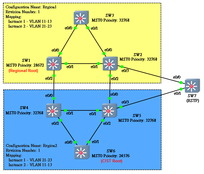
現在我們把眼光放遠一點,如果網絡裡出現另一個 Region,MSTP 又會如何處理呢?首先要重提,各 Region 的 Spanning Tree 互相並不影響 Topology。有趣的是,MSTP 會把這些 Region 當成一隻隻巨大的 Virtual Switch 去看代,請看下圖。
Instance 0 就是 Cisco 預設的 CIST,CIST 將會把整個 Region 變成 Virtual Switch,在此之前,CIST 需要先找出 CIST Root 和 Regional Root。
CIST Root
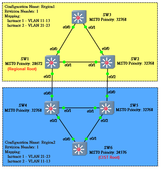
整個網絡 (包含所有 Region) 會揀選一隻 Bridge Prioriy 最低的 Switch 來當 CIST Root,這可以算是 MST 裡的超級 Root 了。擁有這隻超級 Root 的 Virtual Switch 將會成為 CIST 的 Virtual Root Switch。以上圖為例,SW6 因為 Bridge Priority 最小而成為 CIST Root,由於 CIST Root 身處 Region2,因此,Region2 將會成為 Virtual Root Switch。
SW6#show spanning-tree mst 0

##### MST0    vlans mapped:   1-10,14-20,24-4094
Bridge        address aabb.cc00.0600  priority      24576 (24576 sysid 0)
Root          this switch for the CIST
Operational   hello time 2 , forward delay 15, max age 20, txholdcount 6
Configured    hello time 2 , forward delay 15, max age 20, max hops    20

Interface        Role Sts Cost      Prio.Nbr Type
---------------- ---- --- --------- -------- --------------------------------
Et0/0            Desg FWD 2000000   128.1    Shr
Et0/1            Desg FWD 2000000   128.2    Shr
Et0/2            Desg FWD 2000000   128.3    Shr
Regional Root
有連著其他 Region 的 Switch 稱為 Boundary Switch,在 Region1 中,SW1 和 SW2 都是 Boundary Switch。而在 Boundary Switch 中,Bridge Prioriy 最低的 Switch 會再晉升成為 Regional Root。在上圖中 SW1 Bridge Priority 比 SW2 低,因此 SW1 成為 Region1 的 Regional Root。
於是 CIST 就會把兩個 Region 看成兩隻 Virtual Switch,接下來,CIST 就會用和 RSTP/STP 一樣的方法去防止 Loop 發生。
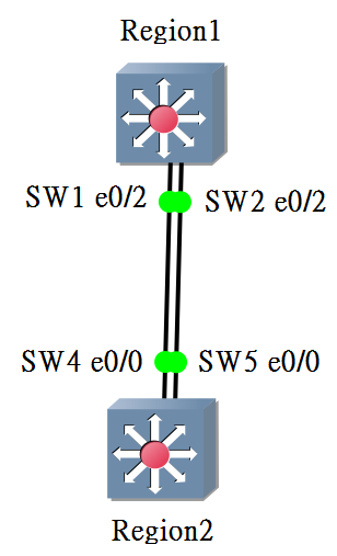
已知 Region2 是 Virtual Root Switch,下一步就要決定 Root Port、Designated Port、Alternate Port 或 Backup Port。CIST 會用以下步驟去決定。
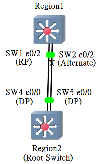
首先,各 Region (除了成為 Virtual Root Switch 的 Region) 的 Regional Root 揀選自己 Root Cost 最小的一個 Port 成為 Root Port,如遇 Root Cost 值相同,則再用其他因素決定,與傳統 STP 方法相同,在此不重覆闡述。所以 SW1 的 e0/2 會成為 Region 1 的 Root Port。
SW1#show spanning-tree mst 0

##### MST0    vlans mapped:   1-10,14-20,24-4094
Bridge        address aabb.cc00.0400  priority      32768 (32768 sysid 0)
Root          address aabb.cc00.0600  priority      24576 (24576 sysid 0)
              port    Et0/2           path cost     2000000
Regional Root this switch
Operational   hello time 2 , forward delay 15, max age 20, txholdcount 6
Configured    hello time 2 , forward delay 15, max age 20, max hops    20

Interface        Role Sts Cost      Prio.Nbr Type
---------------- ---- --- --------- -------- --------------------------------
Et0/0            Desg FWD 2000000   128.1    Shr
Et0/1            Desg FWD 2000000   128.2    Shr
Et0/2            Root FWD 2000000   128.3    Shr
有了 Root Port 後,每一個網段都選 Root Cost 最小的 Port 成為 Designated Port,方法亦與 STP 相同。SW4 e0/0 和 SW5 e0/0 會成為 Designated Port。
SW4#show spanning-tree

MST0
  Spanning tree enabled protocol mstp
  Root ID    Priority    24576
             Address     aabb.cc00.0600
             Cost        0
             Port        3 (Ethernet0/2)
             Hello Time   2 sec  Max Age 20 sec  Forward Delay 15 sec

  Bridge ID  Priority    32768  (priority 32768 sys-id-ext 0)
             Address     aabb.cc00.0200
             Hello Time   2 sec  Max Age 20 sec  Forward Delay 15 sec

Interface           Role Sts Cost      Prio.Nbr Type
------------------- ---- --- --------- -------- --------------------------------
Et0/0               Desg FWD 2000000   128.1 Shr
Et0/1               Desg FWD 2000000   128.2 Shr
Et0/2               Root FWD 2000000   128.3 Shr
SW5#show spanning-tree mst 0

##### MST0    vlans mapped:   1-10,14-20,24-4094
Bridge        address aabb.cc00.0300  priority      32768 (32768 sysid 0)
Root          address aabb.cc00.0200  priority      32768 (32768 sysid 0)
              port    Et0/1           path cost     0
Regional Root address aabb.cc00.0200  priority      32768 (32768 sysid 0)
                                      internal cost 2000000   rem hops 19
Operational   hello time 2 , forward delay 15, max age 20, txholdcount 6
Configured    hello time 2 , forward delay 15, max age 20, max hops    20

Interface        Role Sts Cost      Prio.Nbr Type
---------------- ---- --- --------- -------- --------------------------------
Et0/0            Desg FWD 2000000   128.1    Shr
Et0/1            Root FWD 2000000   128.2    Shr
Et0/2            Desg FWD 2000000   128.3    Shr
最後,其餘的 Port 則會設定為 Alternate Port 或 Backup Port,並把 Port State 變成 Blocking 避免 Loop 發生。揀選方法與 RSTP 相同。
SW2#show spanning-tree mst 0

##### MST0    vlans mapped:   1-10,14-20,24-4094
Bridge        address aabb.cc00.0500  priority      32768 (32768 sysid 0)
Root          address aabb.cc00.0600  priority      24576 (24576 sysid 0)
              port    Et0/1           path cost     2000000
Regional Root address aabb.cc00.0400  priority      32768 (32768 sysid 0)
                                      internal cost 2000000   rem hops 19
Operational   hello time 2 , forward delay 15, max age 20, txholdcount 6
Configured    hello time 2 , forward delay 15, max age 20, max hops    20

Interface        Role Sts Cost      Prio.Nbr Type
---------------- ---- --- --------- -------- --------------------------------
Et0/0            Desg FWD 2000000   128.1    Shr
Et0/1            Root FWD 2000000   128.2    Shr
Et0/2            Altn BLK 2000000   128.3    Shr
於是,網絡就變成以下這個模樣。
與 RSTP 或 STP 並存
由於把使用 RSTP/STP 的網絡改為使用 MSTP 是一項十分浩瀚的工程,難免要分階段進行,以致網絡裡很大機會同時存在 MSTP 和 RSTP/STP 的 Switch。幸好 MSTP 是可以向下兼容 RSTP/STP 的,我們可以試試在上面的 MSTP 網絡中加入一隻 RSTP Switch,看看出現什麼狀況。
如果把 Region1 與 Region2 幻化為 Virtual Switch,便可看得簡單一點,其實就是以下這個模樣,同意嗎?
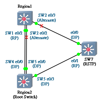
由於 Region2 是 Root Bridge,SW7 e0/1 順理成章成為 Root Port,而 Region 1 與 SW7 之間的網段,就因為 SW7 那邊 Root Cost 較小而勝出成為 DP,這些只是簡單 STP 層面的運算,在此不再詳述了。
比較想跟讀者說明的是關於 BPDU 背後的操作,MSTP 是怎樣相容 RSTP/STP 的呢?由於 MSTP 的 BPDU 是以 Instance 作為單位的,而不是 VLAN,理論上 RSTP/STP 是看不懂由 MSTP 傳來的 BPDU。秘密在於 MSTP 能夠偵測到對方是在運行 MSTP 還是 RSTP/STP,一但發現對方是 RSTP/STP,MSTP 就會把 BPDU 拆散成 Per VLAN 形式發送,如果存在 100 個 VLAN 就發 100 個 BPDU 過去 (事實上和傳統 RSTP/STP 一樣),這樣 SW7 便能夠用 RSTP/STP 來配合了。另外,SW7 當然也可以透過改變 Port 的 STP Cost 來達成 Load Balancing。
那麽,我們可以用新加入的 SW7 來成為 Root 嗎?試試看。
SW7(config)#spanning-tree vlan 1-4094 root primary
出事了!SW2 和 SW5 都會出現 Inconsitent 的訊息,而且把 Port Block 掉。因為 Cisco MSTP 只支緩用 CIST 成為 Root,非常重要,設定時要注意了。
SW5#
*Mar  7 11:59:17.754: %SPANTREE-2-PVSTSIM_FAIL: Blocking root port Et0/3: Inconsitent inferior PVST BPDU received on VLAN 11, claiming root 20491:aabb.cc00.0100
SW5#show spanning-tree

MST0
  Spanning tree enabled protocol mstp
  Root ID    Priority    20481
             Address     aabb.cc00.0100
             Cost        2000000
             Port        4 (Ethernet0/3)
             Hello Time   2 sec  Max Age 20 sec  Forward Delay 15 sec

  Bridge ID  Priority    32768  (priority 32768 sys-id-ext 0)
             Address     aabb.cc00.0300
             Hello Time   2 sec  Max Age 20 sec  Forward Delay 15 sec

Interface           Role Sts Cost      Prio.Nbr Type
------------------- ---- --- --------- -------- --------------------------------
Et0/0               Desg FWD 2000000   128.1    Shr
Et0/1               Desg FWD 2000000   128.2    Shr
Et0/2               Desg FWD 2000000   128.3    Shr
Et0/3               Root BKN*2000000   128.4    Shr Bound(PVST) *PVST_Inc
SW2#
*Mar  7 11:59:17.438: %SPANTREE-2-PVSTSIM_FAIL: Blocking root port Et0/3: Inconsitent inferior PVST BPDU received on VLAN 11, claiming root 20491:aabb.cc00.0100
SW2#show spanning-tree

MST0
  Spanning tree enabled protocol mstp
  Root ID    Priority    20481
             Address     aabb.cc00.0100
             Cost        2000000
             Port        4 (Ethernet0/3)
             Hello Time   2 sec  Max Age 20 sec  Forward Delay 15 sec

  Bridge ID  Priority    32768  (priority 32768 sys-id-ext 0)
             Address     aabb.cc00.0500
             Hello Time   2 sec  Max Age 20 sec  Forward Delay 15 sec

Interface           Role Sts Cost      Prio.Nbr Type
------------------- ---- --- --------- -------- --------------------------------
Et0/0               Desg FWD 2000000   128.1    Shr
Et0/1               Desg FWD 2000000   128.2    Shr
Et0/2               Altn BLK 2000000   128.3    Shr Bound(RSTP)
Et0/3               Root BKN*2000000   128.4    Shr Bound(PVST) *PVST_Inc
用 VTP Version 3 設定 MSTP
MSTP 有一個很麻煩的問題就是那個 VLAN 及 Instance 對應表的設定,由於各 Switch 間的設定必需相同才能讓 Switch 處於同一個 Region。試想想,如果我這個 Region 有一百隻 Switch,每次要動這個設定的時候,豈不是要到所有一百隻 Switch 去更改?這顯然不是理想的做法。解決方法是 VTP Version 3,如果網絡有使用 VTP Version 3 來傳遞 VLAN 設定的話,現在就可以一併傳遞 MSTP 設定了。
關於 VTP Version 3 的理論可看這篇文章。現為以下網絡設定 VTP,假設 SW3 為 VTP Server,SW1 和 SW2 同為 VTP Client。
SW3(config)#vtp domain jannet
Changing VTP domain name from ccie to jannet
SW3(config)#vtp password ccie
Setting device VTP password to ccie
SW3(config)#vtp version 3
SW3(config)#vtp mode server vlan
Setting device to VTP Server mode for VLAN.
SW3(config)#vtp mode server mst
Setting device to VTP Server mode for MST.
SW1(config)#vtp domain jannet
Changing VTP domain name from ccie to jannet
SW1(config)#vtp password ccie
Password already set to ccie
SW1(config)#vtp version 3
SW1(config)#vtp mode client vlan
Setting device to VTP Client mode for VLANS.
SW1(config)#vtp mode client mst
Setting device to VTP Client mode for MST.
SW2(config)#vtp domain jannet
Changing VTP domain name from ccie to jannet
SW2(config)#vtp password ccie
Password already set to ccie
SW2(config)#vtp version 3
SW2(config)#vtp mode client vlan
Setting device to VTP Client mode for VLANS.
SW2(config)#vtp mode client mst
Setting device to VTP Client mode for MST.
以後,要更新 MSTP 設定就可以只在 VTP Server 更新,然後輸入指令 vtp primary mst 升級成 VTP Primary Server,MSTP 設定就會散播到 VTP Client。
SW3#vtp primary mst
This system is becoming primary server for feature  mst
No conflicting VTP3 devices found.
Do you want to continue? [confirm]
SW3#
*Mar  7 12:33:28.789: %SW_VLAN-4-VTP_PRIMARY_SERVER_CHG: aabb.cc00.0700 has become the primary server for the MST VTP feature
更新完成後建議把其免去 Primary Server 的角色,避免發生意外更新。方法是把 VTP mode 改成 Transparent 再改回 Server。
SW3(config)#vtp mode transparent mst
Setting device to VTP Transparent mode for MST.
SW3(config)#vtp mode server mst
Setting device to VTP Server mode for MST.
然而,用 VTP Version 3 發放 MSTP 設定有一點需要注意的,由於每一個 MST Region 的設定是不相同的,因此每個 Region 都需要放於不同的 VTP Domain 之中。
相關主題
Jan Ho 2017-03-04
Posted In: Layer 2 網絡技術, menu-tall-3-zh-hant
發佈留言