目錄
前言
Open Shortest Path First (OSPF) 是屬於 Link-State Routing Protocol,每隻在 OSPF 裡的 Router 都會向 Neighbor 交換自己的 Link-State,當 Router 收到這些 Link-State 之後,就會運用 Dijkstra Algorithm (戴克斯特拉算法) 來計算出最短的路徑 (Shortest Path)。
Area
萬事起頭難,OSPF 有很多仔細的設定等待我們去發掘,現在我們就先要掌握 OSPF 的 Area 概念。OSPF 是設計給一個大型的網絡使用的,為了解決管理上的問題,OSPF 用了一個叫做 Hierarchical System (分層系統),把大型的 OSPF 分割成多個 Area (區域) 去做設定。Area 有兩個表達方式,可以是一個 16 Bits 的數字 (由 0 至 65,535 ),或者用類似 IP 的方式,例如:192.168.1.1,前者比較常見。Area 0 (或 0.0.0.0) 是一個特別的 Area,我們稱為 Backbone Area (骨幹),所有其他 Area 必需與 Backbone Area 連接,這是規矩,不要問,只要信!
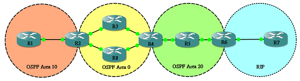
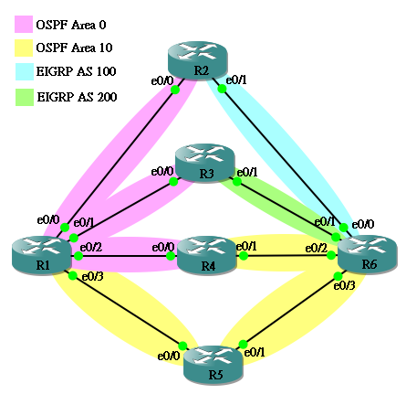
一圖勝萬言!現在來看看以下這個 OSPF 網絡的結構,順道學學一些 OSPF 專屬名詞。
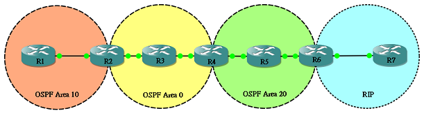
Internal Router
Router 上所有 Interface 都屬於同一個 Area,R3 和 R5 就是 Internal Router。
Backbone Router
最少一個 Interface 連接 Backbone Area (Area 0),所以 R2、R3 和 R4 都是 Backbone Router。
Area Border Router (ABR)
連接兩個 Area 或以上的 Router 稱為 ABR,R2 和 R4 都是 ABR。
Autonomous System Border Routers (ASBR)
有 Interface 連接其他 AS 的 Router 就是 ASBR,在這個網絡中,除了執行 OSPF 之外,最右邊藍色的區域正執行另一種 Routing Protocol RIP,R6 為 OSPF 與 RIP 的連接點,即兩個 AS 的連接點,稱之為 ASBR。
Neighbor 與 Adjacency
來試一試身手,現在嘗試為以下這個簡單的網絡設定 OSPF:
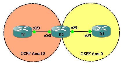
IP 設定如下:
hostname R1
!
interface Ethernet0/0
 ip address 192.168.12.1 255.255.255.0
hostname R2
!
interface Ethernet0/0
 ip address 192.168.12.2 255.255.255.0
!
interface Ethernet0/1
 ip address 192.168.23.2 255.255.255.0
hostname R3
!
interface Ethernet0/1
 ip address 192.168.23.3 255.255.255.0
要設定 OSPF 只需要兩個簡單的步驟:
- 使用 router ospf <process id> 啟動 OSPF,請留意 Process ID 只是本機執行 OSPF Process 的一個 ID,和設定 EIGRP 時的 AS Number 不同,兩隻要成為 Neighbor 的 Router 不需要擁有相同的 ID。
- 使用 network <network no> <wildcard> area <area id> 來宣告那一個 Interface 會參與 OPSF,參與 OSPF 的 Interface 會發佈 Hello packet 嘗試與對方成為 Neighbor,然後再成為 Adjacency,在之後發佈的 link 資訊中亦會包含此網段。
所以,最基本的 OSPF 設定如下:
hostname R1
!
router ospf 1
 network 192.168.12.0 0.0.0.255 area 10
hostname R2
!
router ospf 1
 network 192.168.12.0 0.0.0.255 area 10
 network 192.168.23.0 0.0.0.255 area 0
hostname R3
!
router ospf 1
 network 192.168.23.0 0.0.0.255 area 0
如果成功的話,應該會看到一些像以下的訊息,代表他們成功成為 Neighbor,並由 LOADING 狀態變成 FULL 狀態。
*Mar 1 00:10:32.635: %OSPF-5-ADJCHG: Process 1, Nbr 192.168.23.2 on Ethernet0/0 from LOADING to FULL, Loading Done
你最不希望發生的事發生了,對!Router 們成為 Neighbor 其實中間經過多個 State (狀態),對!背誦如流的話對 Troubleshoot 很有幫助 (對 Cisco 考試有幫助……),各個狀態解釋如下:
Down
沒有發放 Hello Message。
Init
剛剛向對方發放 Hello Message
2-Way
他們開始溝通了!在這時,他們會選出 DR 和 BDR,什麼是 DR 和 BDR 呢?一會在說明。如未能成為 DR 和 BDR,則成為 DROTHER,DROTHER 會停在 2-Way,此時兩隻 Router 已成為 Neighbor。
ExStart
預備交換 Link 資訊。
Exchange
他們正在交換 DBD (Database Descriptors),你可以把 DBD 看成是 Link 資訊的一些目錄,先給目錄對方讓方回覆那些 LSA (Link State Advertisements) 是他需要的。
Loading
正在交換 LSA。
Full
終於完成了!兩隻 Router 成為 Adjacency,在這時,同一個 Area 的 Router 裡面的 Topology Table 應該是完全相同的。
如果想窺探一下狀態轉換的整個過程,可以開啟 debug ip ospf adj,然後使用 clear ip ospf process 來 reset ospf process。
R1#debug ip ospf adj
OSPF adjacency events debugging is on
R1#
R1#clear ip ospf process
Reset ALL OSPF processes? [no]: yes
R1#
*Mar  1 00:30:49.891: OSPF: Interface Ethernet0/0 going Down
*Mar  1 00:30:49.891: OSPF: 192.168.12.1 address 192.168.12.1 on Ethernet0/0 is dead, state DOWN
*Mar  1 00:30:49.895: OSPF: Neighbor change Event on interface Ethernet0/0
*Mar  1 00:30:49.899: OSPF: DR/BDR election on Ethernet0/0
*Mar  1 00:30:49.899: OSPF: Elect BDR 192.168.23.2
*Mar  1 00:30:49.903: OSPF: Elect DR 192.168.23.2
*Mar  1 00:30:49.903: OSPF: Elect BDR 192.168.23.2
*Mar  1 00:30:49.907: OSPF: Elect DR 192.168.23.2
*Mar  1 00:30:49.907:        DR: 192.168.23.2 (Id)   BDR: 192.168.23.2 (Id)
*Mar  1 00:30:49.911: OSPF: Flush network LSA immediately
*Mar  1 00:30:49.911: OSPF: Remember old DR 192.168.12.1 (id)
*Mar  1 00:30:49.915: OSPF: 192.168.23.2 address 192.168.12.2 on Ethernet0/0 is dead, state DOWN
*Mar  1 00:30:49.919: %OSPF-5-ADJCHG: Process 1, Nbr 192.168.23.2 on Ethernet0/0 from FULL to DOWN, Neighbor Down: Interface down or detached

<--這裡開始重新建立 Neighbor-->

*Mar  1 00:30:49.923: OSPF: Neighbor change Event on interface Ethernet0/0
*Mar  1 00:30:49.923: OSPF: DR/BDR election on Ethernet0/0
*Mar  1 00:30:49.923: OSPF: Elect BDR 0.0.0.0
*Mar  1 00:30:49.923: OSPF: Elect DR 0.0.0.0
*Mar  1 00:30:49.923:        DR: none    BDR: none
*Mar  1 00:30:49.923: OSPF: Remember old DR 192.168.23.2 (id)
*Mar  1 00:30:49.931: OSPF: Interface Ethernet0/0 going Up
*Mar  1 00:30:49.951: OSPF: 2 Way Communication to 192.168.23.2 on Ethernet0/0, state 2WAY
*Mar  1 00:30:49.951: OSPF: Backup seen Event before WAIT timer on Ethernet0/0
*Mar  1 00:30:49.955: OSPF: DR/BDR election on Ethernet0/0
*Mar  1 00:30:49.955: OSPF: Elect BDR 192.168.12.1
*Mar  1 00:30:49.959: OSPF: Elect DR 192.168.23.2
*Mar  1 00:30:49.959: OSPF: Elect BDR 192.168.12.1
*Mar  1 00:30:49.963: OSPF: Elect DR 192.168.23.2
*Mar  1 00:30:49.963:        DR: 192.168.23.2 (Id)   BDR: 192.168.12.1 (Id)
*Mar  1 00:30:49.967: OSPF: Send DBD to 192.168.23.2 on Ethernet0/0 seq 0x20AD opt 0x52 flag 0x7 len 32
*Mar  1 00:30:50.111: OSPF: Rcv DBD from 192.168.23.2 on Ethernet0/0 seq 0x241F opt 0x52 flag 0x7 len 32  mtu 1500 state EXSTART
*Mar  1 00:30:50.115: OSPF: NBR Negotiation Done. We are the SLAVE
*Mar  1 00:30:50.115: OSPF: Send DBD to 192.168.23.2 on Ethernet0/0 seq 0x241F opt 0x52 flag 0x0 len 32
*Mar  1 00:30:50.143: OSPF: Rcv DBD from 192.168.23.2 on Ethernet0/0 seq 0x2420 opt 0x52 flag 0x3 len 72  mtu 1500 state EXCHANGE
*Mar  1 00:30:50.147: OSPF: Send DBD to 192.168.23.2 on Ethernet0/0 seq 0x2420 opt 0x52 flag 0x0 len 32
*Mar  1 00:30:50.175: OSPF: Rcv DBD from 192.168.23.2 on Ethernet0/0 seq 0x2421 opt 0x52 flag 0x1 len 32  mtu 1500 state EXCHANGE
*Mar  1 00:30:50.175: OSPF: Exchange Done with 192.168.23.2 on Ethernet0/0
*Mar  1 00:30:50.175: OSPF: Send LS REQ to 192.168.23.2 length 24 LSA count 2
*Mar  1 00:30:50.175: OSPF: Send DBD to 192.168.23.2 on Ethernet0/0 seq 0x2421 opt 0x52 flag 0x0 len 32
*Mar  1 00:30:50.191: OSPF: Rcv LS UPD from 192.168.23.2 on Ethernet0/0 length 92 LSA count 2
*Mar  1 00:30:50.199: OSPF: Synchronized with 192.168.23.2 on Ethernet0/0, state FULL

 <--Output Omitted-->
再來教大家一個重要的指令:show ip ospf neighbor,可以看到現時 neighbor 的狀況,如果在 R2 輸入應該看到以下結果:
R2#show ip ospf neighbor

Neighbor ID     Pri   State           Dead Time   Address         Interface
192.168.23.3      1   FULL/DR         00:00:35    192.168.23.3    Ethernet0/1
192.168.12.1      1   FULL/BDR        00:00:32    192.168.12.1    Ethernet0/0
各欄位解釋如下:
Neighbor ID
即是 Neighbor 的 ID,留意是 ID 不是 IP,即是說,這是對方的「名字」,只不過對方的名字剛好是 IP,此話怎解呢?其實參與 OSPF 的 Router 都會有一個名字,稱為 Router ID,Router ID 會依以下順序來取其名:
- 根據 Router-id 指令來設定
- 如沒有設 Router-id,則使用 Loopback Interface 裡面最大的 IP Address 來做 Router ID
- 如沒有設 Loopback Interface,使用參與 OSPF 的 其他 Interface 裡面最大的 IP Address 來做 Router ID
因此,如果我想刻意去改 Router ID 的話,可以這樣做 (記得要重啟 OSPF):
R1(config)#router ospf 1
R1(config-router)#router-id 1.2.3.4
Reload or use "clear ip ospf process" command, for this to take effect
R1(config-router)#do clear ip ospf process
Reset ALL OSPF processes? [no]: yes
然後在 R2 看看 Neighbor 就會發現 R1 的 Router ID 改變了。
R2#show ip ospf neighbor

Neighbor ID     Pri   State           Dead Time   Address         Interface
192.168.23.3      1   FULL/DR         00:00:38    192.168.23.3    Ethernet0/1
1.2.3.4           1   FULL/BDR        00:00:38    192.168.12.1    Ethernet0/0
Pri
Priority (優先權) 的意思,用來判斷由誰來做 DR,Priority 比較大的 Router 會成為 DR,第二大的會成為 BDR,其他就會成為 DROTHER,至於什麼是 DR 呢?請看下一段。
State
有兩組意思,前面就是剛剛說過的 Neighbor 狀態,如果兩個 Neighbor 能夠保持 FULL 的話就正常了。而後面就是對方的角色,記著是對方,不是自己,現在來解說一下什麼是 DR。話說在 Broadcast Multi-Access 的網絡裡面,例如我們常用的 Ethernet,同一個網段裡面可能同時連接三個或以上的 Router,即是說每隻 Router 需要建立 n-1 條 connection,Fully Mesh 的 connection 總數為 n(n-1)/2。Router 越多 connection 就越多,聰明的 OSPF 就在這些 Router 選一位 DR (Designated Router),所有 Router 只需與 DR 建立 connection。每次有 Routing Update,Router 只需把 Update 傳給 DR,再由 DR 統一發放給其他 Router,這樣,除了 DR 外, Area 裡每隻 Router 只需處理一條 connection。但 DR 有個問題就是如果 DR 出了問題下線了,就無人繼續處理 Routing Update,所以除了 DR 外,還要選一位 BDR (Backup Designated Router),在 DR 下線時由 BDR 頂上變成 DR。
Dead Time
OSPF 預設的 Hello Interval 是 10 秒,即是說 OSPF 會每 10 秒鐘向 Neighbor 傳送 Hello Message,對方接收到後會回應,但如果經過 Dead Interval 40 秒也收不到對方回覆,就判斷對方出了問題下線了。所以在成為 Neighbor 之後,Dead Time 由 40 秒開始倒數,通常數到 30 秒,就會因為收到 Hello Message 而重設為 40 秒,但是如果倒數到 0 秒也收不到 Hello,就判斷對方死了。
Hello Interval 和 Dead Interval 是可以在 Interface 更改的,指令如下。但請緊記要成為 Neighbor,兩隻 Router 的 Interval Timer 必需一致。
R1(config-if)# ip ospf hello-interval 15
R2(config-if)# ip ospf dead-interval 60
Address
就是對方的 IP Address,留意這個 Neighbor ID 不同,是真真正正對方的 IP。
成為 Neighbor 的條件
要成為 Neighbor,兩個 Router 的 Interface 的 OSPF 參數必需相同,這些參數包括:
Area ID
如果我的 Interface 在 Area 0 你的 Interface 在 Area 10,當然就不能成為 Neighbor 了,所以 Area ID 必需相同。
Area Type
OSPF 的 Area 分為幾個種類,分別是:Backbone Area (Area 0)、Standard Area,Stub Area,Totally Stubby Area、Not-so-stubby Area 和 Totally Not-so-stubby Area,不要被他們嚇倒,在稍後的章節會再加以說明,現階段只要知道 Area Type 必需相同便可以。
Prefix 與 Subnet Mask
Interface 的 IP Address 中,Prefix 與 Subnet Mask 必需相同,簡單說,Interface 必需處於同一個網段中才能成為 Neighbor。
Interval Timer
剛才都有提及過,Hello Interval 與 Dead Interval 必需相同。
Authentication
基於保安理由,OSPF 可以設定密碼認證,只有密碼相同才能通過認證成為 Neighbor。OSPF 支緩明碼和 MD5加密密碼兩種認證方式。
要設定明碼,先在兩隻 Router 的 OSPF 設定以下指令:
R1(config)# router ospf 1
R1(config-router)# network 192.168.12.0 0.0.0.255 area 10
R1(config-router)# area 10 authentication
然後在兩隻 Router 的 Interface 設定密碼:
R1(config)# interface Ethernet0/0
R1(config-if)# ip ospf authentication
R1(config-if)# ip ospf authentication-key MyPassword
要設定 MD5 密碼,先在兩隻 Router 的 OSPF 設定以下指令:
R1(config)# router ospf 1
R1(config-router)# network 192.168.12.0 0.0.0.255 area 10
R1(config-router)# area 10 authentication message-digest
然後在兩隻 Router 的 Interface 設定密碼:
R1(config)# interface Ethernet0/0
R1(config-router)# ip ospf message-digest-key 10 md5 MyPassword
Designated Router
現在剖釋一下 DR 和 BDR 的競選條件,知道 DR 的競選方式可以有讓我們有策略地配置 DR,例如使用效能較高的 Router 成為 DR,提高穩定性。
在一個網段中,Priority 較高的 Router 會成為該網段的 DR,第二高會成為 BDR。如果 Priority 相同,Router ID 較高者會成為 DR。現在看看以下實驗,同一個網段有四隻 Router:
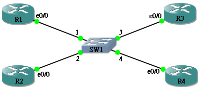
Router 設定如下:
hostname R1
!
interface Ethernet0/0
 ip address 192.168.1.1 255.255.255.0
!
router ospf 1
 network 192.168.1.0 0.0.0.255 area 0
hostname R2
!
interface Ethernet0/0
 ip address 192.168.1.2 255.255.255.0
!
router ospf 1
 network 192.168.1.0 0.0.0.255 area 0
hostname R3
!
interface Ethernet0/0
 ip address 192.168.1.3 255.255.255.0
!
router ospf 1
 network 192.168.1.0 0.0.0.255 area 0
hostname R4
!
interface Ethernet0/0
 ip address 192.168.1.4 255.255.255.0
!
router ospf 1
 network 192.168.1.0 0.0.0.255 area 0
在 R1 看看 Neighbor Table,各 Router 的 Priority 都是 1 (預設值),用 show ip ospf interface <interface> 查看 R1 自己的 Priority 也是 1,由於全部 Router 的 Prioriy 相同,所以 Router ID 192.168.1.4 最大,成為 DR,192.168.1.3 第二大,成為 BDR。
R1#show ip ospf neighbor

Neighbor ID     Pri   State           Dead Time   Address         Interface
192.168.1.2       1   FULL/DROTHER    00:00:38    192.168.1.2     Ethernet0/0
192.168.1.3       1   FULL/BDR        00:00:38    192.168.1.3     Ethernet0/0
192.168.1.4       1   FULL/DR         00:00:37    192.168.1.4     Ethernet0/0

R1#show ip ospf interface ethernet 0/0
Ethernet0/0 is up, line protocol is up
  Internet Address 192.168.1.1/24, Area 0
  Process ID 1, Router ID 192.168.1.1, Network Type BROADCAST, Cost: 10
  Transmit Delay is 1 sec, State DROTHER, Priority 1
  Designated Router (ID) 192.168.1.4, Interface address 192.168.1.4
  Backup Designated router (ID) 192.168.1.3, Interface address 192.168.1.3
  Timer intervals configured, Hello 10, Dead 40, Wait 40, Retransmit 5
    oob-resync timeout 40
    Hello due in 00:00:01
  Supports Link-local Signaling (LLS)
  Index 1/1, flood queue length 0
  Next 0x0(0)/0x0(0)
  Last flood scan length is 0, maximum is 1
  Last flood scan time is 0 msec, maximum is 0 msec
  Neighbor Count is 3, Adjacent neighbor count is 2
    Adjacent with neighbor 192.168.1.3  (Backup Designated Router)
    Adjacent with neighbor 192.168.1.4  (Designated Router)
  Suppress hello for 0 neighbor(s)
要改變 Priority,可以在 Interface 下輸入 ip ospf priority <priority>,試試在 R1 把 Priority 改成 100。
R1(config)#interface ethernet 0/0
R1(config-if)#ip ospf priority 100
雖然 Priority 更改了,但 R1 仍然是 DROTHER,沒有成為 DR,因為已經成為 DR 的 Router 是不會被中途搶走的,所以,如果想要 R1 成為 DR,必需要在 R4 reset OSPF process。
R1#show ip ospf interface ethernet 0/0
Ethernet0/0 is up, line protocol is up
  Internet Address 192.168.1.1/24, Area 0
  Process ID 1, Router ID 192.168.1.1, Network Type BROADCAST, Cost: 10
  Transmit Delay is 1 sec, State DROTHER, Priority 100

<--output omitted-->
用 clear ip ospf process 來 reset OSPF Process。
R4#clear ip ospf process
Reset ALL OSPF processes? [no]: yes
R4#
*Mar  1 00:28:41.175: %OSPF-5-ADJCHG: Process 1, Nbr 192.168.1.1 on Ethernet0/0 from 2WAY to DOWN, Neighbor Down: Interface down or detached
*Mar  1 00:28:41.179: %OSPF-5-ADJCHG: Process 1, Nbr 192.168.1.2 on Ethernet0/0 from 2WAY to DOWN, Neighbor Down: Interface down or detached
*Mar  1 00:28:41.179: %OSPF-5-ADJCHG: Process 1, Nbr 192.168.1.3 on Ethernet0/0 from FULL to DOWN, Neighbor Down: Interface down or detached
再看看 R1,哦?怎樣還不是 DR,但變成 BDR,WHY??
R1#show ip ospf interface ethernet 0/0
Ethernet0/0 is up, line protocol is up
  Internet Address 192.168.1.1/24, Area 0
  Process ID 1, Router ID 192.168.1.1, Network Type BROADCAST, Cost: 10
  Transmit Delay is 1 sec, State BDR, Priority 100

<--output omitted-->
是這樣的,當 R4 下線後,原來的 BDR R3 便會立刻升格成為 DR,R1 就只能由 DROTHER 進升成為 BDR,只有再 Reset R3,R1 才能真正成為 DR。這是一個很好的機制,減少了 DR 出現不穩定的情況。順帶一提,Reset R3 之後,由於 R4 的 router ID 最大,所以成為了新的 BDR。
Reset ALL OSPF processes? [no]: yes
R3#
*Mar  1 00:32:04.415: %OSPF-5-ADJCHG: Process 1, Nbr 192.168.1.1 on Ethernet0/0 from FULL to DOWN, Neighbor Down: Interface down or detached
*Mar  1 00:32:04.419: %OSPF-5-ADJCHG: Process 1, Nbr 192.168.1.2 on Ethernet0/0 from 2WAY to DOWN, Neighbor Down: Interface down or detached
*Mar  1 00:32:04.419: %OSPF-5-ADJCHG: Process 1, Nbr 192.168.1.4 on Ethernet0/0 from EXSTART to DOWN, Neighbor Down: Interface down or detached
R3#
*Mar  1 00:32:04.515: %OSPF-4-NONEIGHBOR: Received database description from unknown neighbor 192.168.1.4
R3#
*Mar  1 00:32:12.799: %OSPF-5-ADJCHG: Process 1, Nbr 192.168.1.1 on Ethernet0/0 from LOADING to FULL, Loading Done
*Mar  1 00:32:12.995: %OSPF-5-ADJCHG: Process 1, Nbr 192.168.1.4 on Ethernet0/0 from LOADING to FULL, Loading Done
R1 成為 DR 了。
R1#show ip ospf interface ethernet 0/0
Ethernet0/0 is up, line protocol is up
  Internet Address 192.168.1.1/24, Area 0
  Process ID 1, Router ID 192.168.1.1, Network Type BROADCAST, Cost: 10
  Transmit Delay is 1 sec, State DR, Priority 100

<--output omitted-->
在 R2 再確認一下 R1 成為 DR。
R2#show ip ospf neighbor

Neighbor ID     Pri   State           Dead Time   Address         Interface
192.168.1.1     100   FULL/DR         00:00:30    192.168.1.1     Ethernet0/0
192.168.1.3       1   FULL/DROTHER    00:00:37    192.168.1.3     Ethernet0/0
192.168.1.4       1   FULL/BDR        00:00:35    192.168.1.4     Ethernet0/0
Network Type
到這一刻為止,我們學習了 OSPF Neighbor 的三大元素:
- Router 透過 Multicast 搜尋 Neighbor
- DR/BDR 的選擇條件 (先比 Prioriy,再比 Router ID)
- Timer 值 (Hello Interval 與 Dead Interval),預設為 10/40 秒
原來 OSPF 會按不同的網絡環境去微調這三大元素!
自動發現 Neighbor / 手動輸入 Neighbor
由於 OSPF 是利用 Multicast 自動發現 Neighbor 的,換句話說,如果網絡不支緩 Broadcast ,等於不支緩 Multicast,就不可以自動發現 Neighbor。毫無疑問,Ethernet 可以支緩 Broadcast,另一種我們最常討論的就是 Frame Relay,究竟 Frame Relay 能否支緩 Broadcast 呢?答案是:YES and NO!不是玩野,因為 Frame Relay Network 的 Broadcast 功能是可以選擇開或關的,如果開了,就支緩 Broadcast,又可自動發現 Neighbor,相反如果關掉,就不支緩 Broadcast,就要手動輸入 Neighbor。
另外要討論的就是 Point to Point Network,由於在 Point to Point Network 裡面,雖然沒有 Broadcast,但建立 Point to Point connection 的兩個 Node 絕對知道對方存在,因此仍會自動建立 Neighbor,其中一個例子為透過 Serial Interface Point to Point Connection 建立 OSPF Neighbor。
因此,結論是:
現在我們用一個 Multipoint Non-Broadcast 的 Frame Relay Network 來作示範,看看要怎樣手動設定 Neighbor。接下來會有一些關於 Frame Relay 的設定,如果讀者不熟悉的話,可以先看看本網的 Frame Relay Switching 教學。
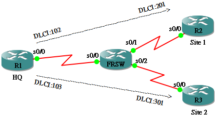
hostname R1
!
interface Serial0/0
 ip address 192.168.123.1 255.255.255.0
 encapsulation frame-relay
 frame-relay map ip 192.168.123.2 102
 frame-relay map ip 192.168.123.3 103
hostname R2
!
interface Serial0/0
 ip address 192.168.123.2 255.255.255.0
 encapsulation frame-relay
 frame-relay map ip 192.168.123.1 201
 frame-relay map ip 192.168.123.3 201
hostname R3
!
interface Serial0/0
 ip address 192.168.123.3 255.255.255.0
 encapsulation frame-relay
 frame-relay map ip 192.168.123.1 301
 frame-relay map ip 192.168.123.2 301
由於 frame-relay 指令沒有 Broadcast 這個 keyword,所以此網絡不支緩 Broadcast。我們嘗試在這些 Router 執行 OSPF 的指令。
hostname R1
!
router ospf 1
 network 192.168.123.0 0.0.0.255 area 0
hostname R2
!
router ospf 1
 network 192.168.123.0 0.0.0.255 area 0
hostname R3
!
router ospf 1
 network 192.168.123.0 0.0.0.255 area 0
指令是輸入了,可惜的是,就算你等到 2046,Neighbor 也不會建立起來,因為不支緩 Broadcast,這時就要手動去建立 Neighbor,指令如下:
R1(config)#router ospf 1
R1(config-router)#neighbor 192.168.123.2
R1(config-router)#neighbor 192.168.123.3
R1(config-router)#
*Mar  1 00:28:05.083: %OSPF-5-ADJCHG: Process 1, Nbr 192.168.123.2 on Serial0/0 from LOADING to FULL, Loading Done
*Mar  1 00:28:06.083: %OSPF-5-ADJCHG: Process 1, Nbr 192.168.123.3 on Serial0/0 from LOADING to FULL, Loading Done
決定是否要選 DR/BDR
DR 是否一定要選呢?細心想一想,在上一節提及的網絡裡說過,選 DR 的原因是什麼呢?是因為不想建立太多 connection。如果只有兩隻 Router 呢?對!就不用選了,因為兩隻 Router 就只有一條 connection,根本不用擔心有太多 connection 這個問題,所以不用選,這樣只有兩隻 Router 的網絡我們叫作 Point To Point Network。這樣說都不夠正宗,應該說如果像 Ethernet 這種 Multi Access 的 Network 才需要選 DR。那麽,除了 Ethernet,還有那種 Network 有 Multi Access 這種特性呢?
例如一種叫 Fully Mesh 的 Multipoint Frame Relay Network,他們透過 Frame Relay Switches 來連接,並非 Ethernet 網絡,但每隻 Router 卻可以連接其他所有 Router,保留了 Ethernet 中 Multi Access 的能力。
所以,結論是:
還記得我們可以干擾 DR/BDR 的選舉嗎?如果你還記得的話,我們是可以用 ip ospf priority 來改變 Router 的 priority 來控制選舉結果,但 ip ospf priority 是透過 Hello Message 來傳送的,Hello Message 依賴 Broadcast,如果網絡是 Non-Broadcast 我們又可以怎樣控制 Priority?有方法的,剛才教你的 neighbor 指令是可以加入一個 priority 參數去改變 priority 的,方法如下:
R1(config)#router ospf 1
R1(config-router)#neighbor 192.168.123.2 priority 50
R1(config-router)#neighbor 192.168.123.3 priority 100
控制 Timer
為什麼要控制 Timer?因為不同網絡的網絡頻寬和遲緩時間 (delay) 情況不一,Neighbor 要靠 Hello Message 去維持,預設情況下,Hello 每 10 秒鐘傳送一次 (Hello Interval),40 秒收不到 Hello 的話就中斷 Neighbor 關係 (Dead Interval),這是適合像 Broadcast Multi-access (Ethernet) 和 Point to Point 這些高速網絡的設定,在效能較低的網絡,就要改成 Hello Interval 30 秒,Dead Interval 120 秒的設定提供較大的容忍度。
小結
自動 / 手動Neighbor、 DR 選舉與否、10,40 / 30,120 Timer 設定 這三大元素,Cisco Router 把不同的設定組合歸納為五種模式,我們把這玩意稱呼為 Network Type。下表列出五種模式各個不同的設定:
| Non-Broadcast Multi-access (NBMA) | Multipoint Broadcast | Multipoint Non-Broadcast | Broadcast Multi-access | Point-to-Point | |
|---|---|---|---|---|---|
| DR / BDR 選舉 | Yes | No | No | Yes | No |
| 自動發現 Neighbor | No | Yes | No | Yes | Yes |
| Hello / Dead Interval | 30 / 120 | 30 / 120 | 30 / 120 | 10 / 40 | 10 / 40 |
| 網絡例子 | Fully Mesh Frame Relay | Multipoint Frame Relay (有 Broadcast Keyword) | Multipoint Frame Relay (無 Broadcast Keyword) | Ethernet | Serial Interface Point to Point Connection |
如果是 Ethernet Interface,預設是使用 Broadcast Multi-access,使用 show ip ospf interface 就會見到。
R1#show ip ospf interface
Ethernet0/0 is up, line protocol is up
  Internet Address 192.168.12.1/24, Area 0
  Process ID 1, Router ID 192.168.12.1, Network Type BROADCAST, Cost: 10
  Transmit Delay is 1 sec, State DR, Priority 1
  Designated Router (ID) 192.168.12.1, Interface address 192.168.12.1
  No backup designated router on this network
  Timer intervals configured, Hello 10, Dead 40, Wait 40, Retransmit 5
    oob-resync timeout 40
    Hello due in 00:00:05
  Supports Link-local Signaling (LLS)
  Index 1/1, flood queue length 0
  Next 0x0(0)/0x0(0)
  Last flood scan length is 0, maximum is 0
  Last flood scan time is 0 msec, maximum is 0 msec
  Neighbor Count is 0, Adjacent neighbor count is 0
  Suppress hello for 0 neighbor(s)
在 Interface 輸入指令 ip ospf network <network type> 可以更改 Network Type。
R1(config)#interface ethernet 0/0
R1(config-if)#ip ospf network ?
  broadcast            Specify OSPF broadcast multi-access network
  non-broadcast        Specify OSPF NBMA network
  point-to-multipoint  Specify OSPF point-to-multipoint network
  point-to-point       Specify OSPF point-to-point network

R1(config-if)#ip ospf network non-broadcast
R1(config-if)#end
R1#show ip ospf interface
Ethernet0/0 is up, line protocol is up
  Internet Address 192.168.12.1/24, Area 0
  Process ID 1, Router ID 192.168.12.1, Network Type NON_BROADCAST, Cost: 10
  Transmit Delay is 1 sec, State WAITING, Priority 1
  No designated router on this network
  No backup designated router on this network
  Timer intervals configured, Hello 30, Dead 120, Wait 120, Retransmit 5
    oob-resync timeout 120
    Hello due in 00:00:17
    Wait time before Designated router selection 00:01:17
  Supports Link-local Signaling (LLS)
  Index 1/1, flood queue length 0
  Next 0x0(0)/0x0(0)
  Last flood scan length is 0, maximum is 0
  Last flood scan time is 0 msec, maximum is 0 msec
  Neighbor Count is 0, Adjacent neighbor count is 0
  Suppress hello for 0 neighbor(s)
Link-state Advertisement (LSA)
OSPF 是一個 Link-state Routing Protocol,所謂 Link-state 的 Link 簡單來說就是 Router 的 Interface,OSPF 的運作原理就是把自己每個 Interface 正連著什麼 Network 告訴其他 Router,於是 Router 便可計算出自己的 Route Table。LSA 中包括了幾項重要的資訊,包括:LSA 由誰傳送出來的、它告訴我連著什麼 Network、以及它要去這 Network 的 Cost (Cost 是在有多於一條路徑時用來判斷走那條路較快,在稍後說到 Cost 的章節時再加以說明),然後每個 Router 收集了這些 Link-state 就能計算出去不同 Network 要走的路徑和 Cost。LSA 有不同的類型 (Type),此部份會用以下網絡為例子解釋每一個類型的 LSA。由於文章早段已說明 OSPF 的設定方法,在此不再詳述。另外,為了設定 Router ID,每隻 Router 都設了 Loopback Interface IP,R1 為 1.1.1.1,R2 為 2.2.2.2,如此類推。
hostname R1
!
router ospf 1
 network 192.168.12.0 0.0.0.255 area 10
hostname R2
!
router ospf 1
 network 192.168.12.0 0.0.0.255 area 10
 network 192.168.23.0 0.0.0.255 area 0
 network 192.168.28.0 0.0.0.255 area 0
hostname R3
!
router ospf 1
 network 192.168.23.0 0.0.0.255 area 0
 network 192.168.34.0 0.0.0.255 area 0
hostname R4
!
router ospf 1
 network 192.168.34.0 0.0.0.255 area 0
 network 192.168.48.0 0.0.0.255 area 0
 network 192.168.45.0 0.0.0.255 area 20
hostname R5
!
router ospf 1
 network 192.168.45.0 0.0.0.255 area 20
 network 192.168.56.0 0.0.0.255 area 20
R6 設定較特別,因為 R6 的角色是 ASBR,我們用到 redistribute 指令,而 redistribute 並非本篇討論範圍,在此不詳細解釋,大家只要了解 redistribute 是要把 RIP 的 Route 匯入 OSPF 之中,相反,也把 OSPF 的 Route 匯入 RIP 之中。
hostname R6
!
router ospf 1
 redistribute rip subnets
 network 192.168.56.0 0.0.0.255 area 20
!
router rip
 version 2
 redistribute ospf 1 metric 1
 network 192.168.67.0
R7 只純粹執行 RIP,並非 OSPF Network 之中。
hostname R7
!
router rip
 version 2
 network 192.168.67.0
hostname R8
!
router ospf 1
 network 192.168.28.0 0.0.0.255 area 0
 network 192.168.48.0 0.0.0.255 area 0
Router LSA (Type 1)
Router LSA 是在同一個 Area 裡面所有 Router (包括自己) 送來的 Link-State,要看 Type 1 LSA,可以在 Router 輸入指令 show ip ospf database router,以下用 R1 作例子,可見 R1 收到兩條 Type 1 LSA,留意 Advertising Router 這一欄,第一條從 1.1.1.1 (即自己) 發出,另一條從 2.2.2.2 發出。集中觀察第二條,看看 2.2.2.2 (即 R2) 告訴 R1 什麼?R2 告訴 主要 R1 兩件事:
- 我是一隻 ABR
- 我要告訴你我連著一條 Link,就是 192.168.12.2,我到它那裡需要 Cost 10。
R1#show ip ospf 1 database router

            OSPF Router with ID (1.1.1.1) (Process ID 1)

                Router Link States (Area 10)

  LS age: 234
  Options: (No TOS-capability, DC)
  LS Type: Router Links
  Link State ID: 1.1.1.1
  Advertising Router: 1.1.1.1
  LS Seq Number: 80000002
  Checksum: 0x1C18
  Length: 36
  Number of Links: 1

    Link connected to: a Transit Network
     (Link ID) Designated Router address: 192.168.12.1
     (Link Data) Router Interface address: 192.168.12.1
      Number of TOS metrics: 0
       TOS 0 Metrics: 10


  Routing Bit Set on this LSA
  LS age: 254
  Options: (No TOS-capability, DC)
  LS Type: Router Links
  Link State ID: 2.2.2.2
  Advertising Router: 2.2.2.2
  LS Seq Number: 80000002
  Checksum: 0xE049
  Length: 36
  Area Border Router
  Number of Links: 1

    Link connected to: a Transit Network
     (Link ID) Designated Router address: 192.168.12.1
     (Link Data) Router Interface address: 192.168.12.2
      Number of TOS metrics: 0
       TOS 0 Metrics: 10
Network LSA (Type 2)
Network LSA 是由每個網段的 DR 發給其他 Router,告訴它們 DR 正連著那些 Router。要看 Type 2 LSA,可以在 Router 輸入指令 show ip ospf database network,以下用 R1 作例子。因為 R2 是 DR,所以 R1 收到 R2 傳來的 Type 2,在 Type 2 裡,我們看見 R2 正連著 1.1.1.1 和 2.2.2.2 (R2 自己)。
R1#show ip ospf neighbor

Neighbor ID     Pri   State           Dead Time   Address         Interface
2.2.2.2           1   FULL/DR         00:00:35    192.168.12.2    Ethernet0/0
R1#
R1#show ip ospf 1 database network

            OSPF Router with ID (1.1.1.1) (Process ID 1)

                Net Link States (Area 10)

  Routing Bit Set on this LSA
  LS age: 26
  Options: (No TOS-capability, DC)
  LS Type: Network Links
  Link State ID: 192.168.12.2 (address of Designated Router)
  Advertising Router: 2.2.2.2
  LS Seq Number: 80000001
  Checksum: 0x8F1F
  Length: 32
  Network Mask: /24
        Attached Router: 2.2.2.2
        Attached Router: 1.1.1.1
Network Summary LSA (Type 3)
由 ABR 產生,告訴 Area 內的 Router 從它那裡可以到達那些 Network 以及 Cost。要看 Type 3 LSA,可以在 Router 輸入指令 show ip ospf database summary,以下用 R1 作例子。R1 收到 6 條 Type 3,全部來自 R2 (2.2.2.2),R2 告訴 R1:
- 從我這裡可以到達 192.168.23.0,Cost 是 10。
- 從我這裡可以到達 192.168.28.0,Cost 是 10。
- 從我這裡可以到達 192.168.34.0,Cost 是 20。
- 從我這裡可以到達 192.168.45.0,Cost 是 30。
- 從我這裡可以到達 192.168.48.0,Cost 是 20。
- 從我這裡可以到達 192.168.56.0,Cost 是 40。
R1#show ip ospf 1 database summary

            OSPF Router with ID (1.1.1.1) (Process ID 1)

                Summary Net Link States (Area 10)

  Routing Bit Set on this LSA
  LS age: 207
  Options: (No TOS-capability, DC, Upward)
  LS Type: Summary Links(Network)
  Link State ID: 192.168.23.0 (summary Network Number)
  Advertising Router: 2.2.2.2
  LS Seq Number: 80000002
  Checksum: 0xFFA9
  Length: 28
  Network Mask: /24
        TOS: 0  Metric: 10

  Routing Bit Set on this LSA
  LS age: 125
  Options: (No TOS-capability, DC, Upward)
  LS Type: Summary Links(Network)
  Link State ID: 192.168.28.0 (summary Network Number)
  Advertising Router: 2.2.2.2
  LS Seq Number: 80000001
  Checksum: 0xCADA
  Length: 28
  Network Mask: /24
        TOS: 0  Metric: 10

  Routing Bit Set on this LSA
  LS age: 207
  Options: (No TOS-capability, DC, Upward)
  LS Type: Summary Links(Network)
  Link State ID: 192.168.34.0 (summary Network Number)
  Advertising Router: 2.2.2.2
  LS Seq Number: 80000002
  Checksum: 0xEAA9
  Length: 28
  Network Mask: /24
        TOS: 0  Metric: 20

  Routing Bit Set on this LSA
  LS age: 213
  Options: (No TOS-capability, DC, Upward)
  LS Type: Summary Links(Network)
  Link State ID: 192.168.45.0 (summary Network Number)
  Advertising Router: 2.2.2.2
  LS Seq Number: 80000002
  Checksum: 0xD5A9
  Length: 28
  Network Mask: /24
        TOS: 0  Metric: 30

   Routing Bit Set on this LSA
  LS age: 90
  Options: (No TOS-capability, DC, Upward)
  LS Type: Summary Links(Network)
  Link State ID: 192.168.48.0 (summary Network Number)
  Advertising Router: 2.2.2.2
  LS Seq Number: 80000002
  Checksum: 0x5036
  Length: 28
  Network Mask: /24
        TOS: 0  Metric: 20

  Routing Bit Set on this LSA
  LS age: 218
  Options: (No TOS-capability, DC, Upward)
  LS Type: Summary Links(Network)
  Link State ID: 192.168.56.0 (summary Network Number)
  Advertising Router: 2.2.2.2
  LS Seq Number: 80000002
  Checksum: 0xC0A9
  Length: 28
  Network Mask: /24
        TOS: 0  Metric: 40
ASBR Summary (Type 4)
ASBR Summary 也是由 ABR 產生,告訴 Area 內的 Router 從它那裡可以到達那些 ASBR 以及 Cost。要看 Type 4 LSA,可以在 Router 輸入指令 show ip ospf database asbr-summary,以下用 R1 作例子。R1 只收到一條 Type 4,R2 告訴 R1 從它那裡可以到達一隻叫 6.6.6.6 的 ASBR,Cost 是 40。
R1#show ip ospf 1 database asbr-summary

            OSPF Router with ID (1.1.1.1) (Process ID 1)

                Summary ASB Link States (Area 10)

  Routing Bit Set on this LSA
  LS age: 701
  Options: (No TOS-capability, DC, Upward)
  LS Type: Summary Links(AS Boundary Router)
  Link State ID: 6.6.6.6 (AS Boundary Router address)
  Advertising Router: 2.2.2.2
  LS Seq Number: 80000002
  Checksum: 0xB939
  Length: 28
  Network Mask: /0
        TOS: 0  Metric: 40
External LSA (Type 5)
External LSA 是由 ASBR 產生的,告訴所有 Area (除了 Stub Area,稍後再說明) 裡的所有 Router,從它那裡可以到達那些 External Network (即不是屬於這個 OSPF 的),要看 Type 5 LSA,可以在 Router 輸入指令 show ip ospf database external,以下用 R1 作例子。R1 只收到一條來自遠方的 R6(6.6.6.6) 所發佈的 Type 5,告訴 R1 從它那裡可以到達 192.168.67.0 這個 Network,Cost 是 20,而 Metric Type 是 2,又稱 E2。Metric Type 是什麼呢?而從 R1 去到 R6 要走這麽遠,為什麼 Metric 是 20 呢?在此先賣個關子,等到講解 Cost 的部份在詳細說明。
R1#show ip ospf 1 database external

            OSPF Router with ID (1.1.1.1) (Process ID 1)

                Type-5 AS External Link States

  LS age: 14
  Options: (No TOS-capability, DC)
  LS Type: AS External Link
  Link State ID: 192.168.67.0 (External Network Number )
  Advertising Router: 6.6.6.6
  LS Seq Number: 80000003
  Checksum: 0x9940
  Length: 36
  Network Mask: /24
        Metric Type: 2 (Larger than any link state path)
        TOS: 0
        Metric: 20
        Forward Address: 0.0.0.0
        External Route Tag: 0
於是,OSPF 的 Router 們就會依據收回來的 Link-state 計算出自己的 Route Table,現在我們看一下 R3 的 Route Table 看看得出來的結果。用 OSPF 計出來的 Route 用 O 來表示,如果有 IA 則代表這 Route 是要「跨區」的 Route,需要經過 ABR。如果有 E1 或 E2 則代表這 Route 是 External Route,需要經過 ASBR。110 是 AD (Administrative Distance),而 AD 後面的數字則是該 Router 的 OSPF Metric,Metric 跟 Cost 有關,留在稍後章節再說。
R3#show ip route
Codes: C - connected, S - static, R - RIP, M - mobile, B - BGP
       D - EIGRP, EX - EIGRP external, O - OSPF, IA - OSPF inter area
       N1 - OSPF NSSA external type 1, N2 - OSPF NSSA external type 2
       E1 - OSPF external type 1, E2 - OSPF external type 2
       i - IS-IS, su - IS-IS summary, L1 - IS-IS level-1, L2 - IS-IS level-2
       ia - IS-IS inter area, * - candidate default, U - per-user static route
       o - ODR, P - periodic downloaded static route

Gateway of last resort is not set

O IA 192.168.12.0/24 [110/20] via 192.168.23.2, 00:10:51, Ethernet0/1
O    192.168.28.0/24 [110/20] via 192.168.23.2, 00:10:51, Ethernet0/1
     3.0.0.0/32 is subnetted, 1 subnets
C       3.3.3.3 is directly connected, Loopback0
O IA 192.168.45.0/24 [110/20] via 192.168.34.4, 00:10:51, Ethernet0/0
O IA 192.168.56.0/24 [110/30] via 192.168.34.4, 00:10:51, Ethernet0/0
C    192.168.23.0/24 is directly connected, Ethernet0/1
O E2 192.168.67.0/24 [110/20] via 192.168.34.4, 00:10:51, Ethernet0/0
C    192.168.34.0/24 is directly connected, Ethernet0/0
O    192.168.48.0/24 [110/20] via 192.168.34.4, 00:10:56, Ethernet0/0
另外還有一種 Type 7 的 LSA,筆者打算在介紹 NSSA 的章節才向讀者說明,各種 LSA 總結如下表:
| Type 1 | Type 2 | Type 3 | Type 4 | Type 5 | Type 7 | |
|---|---|---|---|---|---|---|
| 由誰發放 | 所有 Router | 每個網段的 DR | ABR | ABR | ASBR | ASBR |
| 由誰接收 | 同一 Area 內的其他 Router | 同一 Area 內的Non-DR Router | 同一 Area 內其他 Router | 同一 Area 內其他 Router | OSPF 內所有 Router | NSSA 內的 Router |
| 包含什麽資訊 | 連接著的 Network 資訊 | DR 連接著的 Router 資訊 | 位於其他 Area 的 Network 資訊 | ASBR 資訊 | External Network 資訊 | External Network 資訊 |
Stub Area
再拿上一個章節的網絡來討論,先看看 R1 的 Route Table 和 OSPF Database。
R1#show ip route | begin Gateway
Gateway of last resort is not set

C    192.168.12.0/24 is directly connected, Ethernet0/0
     1.0.0.0/32 is subnetted, 1 subnets
C       1.1.1.1 is directly connected, Loopback0
O IA 192.168.28.0/24 [110/20] via 192.168.12.2, 00:26:29, Ethernet0/0
O IA 192.168.45.0/24 [110/40] via 192.168.12.2, 01:19:14, Ethernet0/0
O IA 192.168.56.0/24 [110/50] via 192.168.12.2, 01:19:14, Ethernet0/0
O IA 192.168.23.0/24 [110/20] via 192.168.12.2, 01:19:14, Ethernet0/0
O E2 192.168.67.0/24 [110/20] via 192.168.12.2, 00:26:01, Ethernet0/0
O IA 192.168.34.0/24 [110/30] via 192.168.12.2, 01:19:14, Ethernet0/0
O IA 192.168.48.0/24 [110/30] via 192.168.12.2, 00:25:48, Ethernet0/0

R1#show ip ospf 1 database

            OSPF Router with ID (1.1.1.1) (Process ID 1)

                Router Link States (Area 10)

Link ID         ADV Router      Age         Seq#       Checksum Link count
1.1.1.1         1.1.1.1         11          0x8000000A 0x009A8A 2
2.2.2.2         2.2.2.2         17          0x80000009 0x00DC45 1

                Net Link States (Area 10)

Link ID         ADV Router      Age         Seq#       Checksum
192.168.12.1    1.1.1.1         21          0x80000001 0x00C7EB
192.168.12.2    2.2.2.2         17          0x80000007 0x008325

                Summary Net Link States (Area 10)

Link ID         ADV Router      Age         Seq#       Checksum
192.168.23.0    2.2.2.2         22          0x80000006 0x00F7AD
192.168.28.0    2.2.2.2         22          0x80000004 0x00C4DD
192.168.34.0    2.2.2.2         22          0x80000006 0x00E2AD
192.168.45.0    2.2.2.2         22          0x80000006 0x00CDAD
192.168.48.0    2.2.2.2         22          0x80000005 0x004A39
192.168.56.0    2.2.2.2         22          0x80000006 0x00B8AD

                Summary ASB Link States (Area 10)

Link ID         ADV Router      Age         Seq#       Checksum
6.6.6.6         2.2.2.2         26          0x80000001 0x00BB38

                Type-5 AS External Link States

Link ID         ADV Router      Age         Seq#       Checksum Tag
192.168.67.0    6.6.6.6         1282        0x80000004 0x009741 0
好像不錯喔!收到 Type 1 至 Type 5 的 LSA,然後產生出 Route Table,每一個 Network 都通了,還有什麼問題呢?請大家試試站在 R1 的角度看世界。對於 R1 來說,無論去那一個 Network,Next Hop 都是 192.168.12.2 是不是?那麽,它為什麼還這麽苦惱要記著那麽多條 Route 呢?對!所以,聰明的 OSPF 設計者也想到了這個問題,所以發明了 Stub Area 這東西來。我們試試把 Area 10 設定成 Stub Area,看看帶來什麽變化。指令非常簡單,只要在 OSPF 設定中加一句 area <area no> stub 便可以。
hostname R1
!
router ospf 1
 area 10 stub
 network 192.168.12.0 0.0.0.255 area 10
hostname R2
!
router ospf 1
 area 10 stub
 network 192.168.12.0 0.0.0.255 area 10
 network 192.168.23.0 0.0.0.255 area 0
 network 192.168.28.0 0.0.0.255 area 0
現在再看看 R1 的 Route Table,External Route 不見了!取而代之的是多了一條叫 O*IA 的 Default Route,為什麽呢?
R1#show ip route | begin Gateway
Gateway of last resort is 192.168.12.2 to network 0.0.0.0

C    192.168.12.0/24 is directly connected, Ethernet0/0
     1.0.0.0/32 is subnetted, 1 subnets
C       1.1.1.1 is directly connected, Loopback0
O IA 192.168.28.0/24 [110/20] via 192.168.12.2, 00:00:06, Ethernet0/0
O IA 192.168.45.0/24 [110/40] via 192.168.12.2, 00:00:06, Ethernet0/0
O IA 192.168.56.0/24 [110/50] via 192.168.12.2, 00:00:06, Ethernet0/0
O IA 192.168.23.0/24 [110/20] via 192.168.12.2, 00:00:06, Ethernet0/0
O IA 192.168.34.0/24 [110/30] via 192.168.12.2, 00:00:06, Ethernet0/0
O IA 192.168.48.0/24 [110/30] via 192.168.12.2, 00:00:06, Ethernet0/0
O*IA 0.0.0.0/0 [110/11] via 192.168.12.2, 00:00:06, Ethernet0/0
OSPF Database 一定發生了什麼事,快看看。原來 Stub Area 可以禁止 Type 4 和 Type 5 的 LSA 進入該區,並且 ABR 會發出一條 0.0.0.0 (Default Route) 的 Type 3,所以就得出 Route Table 的結果了。
R1#show ip ospf 1 database

            OSPF Router with ID (1.1.1.1) (Process ID 1)

                Router Link States (Area 10)

Link ID         ADV Router      Age         Seq#       Checksum Link count
1.1.1.1         1.1.1.1         140         0x8000000C 0x0030FA 1
2.2.2.2         2.2.2.2         138         0x8000000B 0x00F62B 1

                Net Link States (Area 10)

Link ID         ADV Router      Age         Seq#       Checksum
192.168.12.2    2.2.2.2         138         0x80000009 0x009D0B

                Summary Net Link States (Area 10)

Link ID         ADV Router      Age         Seq#       Checksum
0.0.0.0         2.2.2.2         143         0x80000001 0x0075C0
192.168.23.0    2.2.2.2         143         0x80000007 0x001492
192.168.28.0    2.2.2.2         143         0x80000005 0x00E0C2
192.168.34.0    2.2.2.2         143         0x80000007 0x00FE92
192.168.45.0    2.2.2.2         143         0x80000007 0x00E992
192.168.48.0    2.2.2.2         143         0x80000006 0x00661E
192.168.56.0    2.2.2.2         143         0x80000007 0x00D492
需然有一點改善,但 R1 的 Route Table 似乎還可以再簡化一點吧!那麽,現在就再介紹你一個叫 Totally Stubby Area,設定方法如下。
hostname R1
!
router ospf 1
 area 10 stub no-summary
 network 192.168.12.0 0.0.0.255 area 10
hostname R2
!
router ospf 1
 area 10 stub no-summary
 network 192.168.12.0 0.0.0.255 area 10
 network 192.168.23.0 0.0.0.255 area 0
 network 192.168.28.0 0.0.0.255 area 0
對 R1 的 OSPF Database 帶來的改變是……
R1#show ip ospf 1 database

            OSPF Router with ID (1.1.1.1) (Process ID 1)

                Router Link States (Area 10)

Link ID         ADV Router      Age         Seq#       Checksum Link count
1.1.1.1         1.1.1.1         465         0x8000000C 0x0030FA 1
2.2.2.2         2.2.2.2         462         0x8000000B 0x00F62B 1

                Net Link States (Area 10)

Link ID         ADV Router      Age         Seq#       Checksum
192.168.12.2    2.2.2.2         462         0x80000009 0x009D0B

                Summary Net Link States (Area 10)

Link ID         ADV Router      Age         Seq#       Checksum
0.0.0.0         2.2.2.2         81          0x80000002 0x0073C1
原來在 Totally Stubby Area 裡,除了 0.0.0.0 之外的所有 Type 3 也禁止了,所以得出的 Route Table 如下:
R1#show ip route | begin Gateway
Gateway of last resort is 192.168.12.2 to network 0.0.0.0

C    192.168.12.0/24 is directly connected, Ethernet0/0
     1.0.0.0/32 is subnetted, 1 subnets
C       1.1.1.1 is directly connected, Loopback0
O*IA 0.0.0.0/0 [110/11] via 192.168.12.2, 00:02:37, Ethernet0/0
由此可見,Stub Area 與 Totally Stubby Area 能有效減少 LSA 的傳送,減低對網絡帶來的負荷,也簡化了 Route Table,在管理的角度來說是個好處。不過 Stub Area 和 Totally Stubby Area 只適合這種「沒有連著 External Network」的 Area。
Not So Stubby Area (NSSA)
本章節的研究像為 Area 20,先看看 R5 的 Route Table 和 OSPF Database。
R5#show ip route | begin Gateway
Gateway of last resort is not set

O IA 192.168.12.0/24 [110/40] via 192.168.45.4, 00:18:55, Ethernet0/1
O IA 192.168.28.0/24 [110/30] via 192.168.45.4, 00:57:29, Ethernet0/1
C    192.168.45.0/24 is directly connected, Ethernet0/1
     5.0.0.0/32 is subnetted, 1 subnets
C       5.5.5.5 is directly connected, Loopback0
C    192.168.56.0/24 is directly connected, Ethernet0/0
O IA 192.168.23.0/24 [110/30] via 192.168.45.4, 01:15:58, Ethernet0/1
O E2 192.168.67.0/24 [110/20] via 192.168.56.6, 00:58:12, Ethernet0/0
O IA 192.168.34.0/24 [110/20] via 192.168.45.4, 01:15:58, Ethernet0/1
O IA 192.168.48.0/24 [110/20] via 192.168.45.4, 00:58:17, Ethernet0/1
R5#show ip ospf 1 database

            OSPF Router with ID (5.5.5.5) (Process ID 1)

                Router Link States (Area 20)

Link ID         ADV Router      Age         Seq#       Checksum Link count
4.4.4.4         4.4.4.4         1687        0x80000005 0x005F6F 1
5.5.5.5         5.5.5.5         681         0x80000009 0x003626 2
6.6.6.6         6.6.6.6         574         0x80000007 0x00D4CE 1

                Net Link States (Area 20)

Link ID         ADV Router      Age         Seq#       Checksum
192.168.45.5    5.5.5.5         1664        0x80000004 0x00A1C1
192.168.56.5    5.5.5.5         681         0x80000003 0x008EC2

                Summary Net Link States (Area 20)

Link ID         ADV Router      Age         Seq#       Checksum
192.168.12.0    4.4.4.4         1165        0x80000008 0x00F998
192.168.23.0    4.4.4.4         1687        0x80000004 0x002471
192.168.28.0    4.4.4.4         1432        0x80000003 0x00EEA2
192.168.34.0    4.4.4.4         1687        0x80000004 0x00464E
192.168.48.0    4.4.4.4         1687        0x80000002 0x00AFD8

                Type-5 AS External Link States

Link ID         ADV Router      Age         Seq#       Checksum Tag
192.168.67.0    6.6.6.6         581         0x80000005 0x009542 0
很想化繁為簡吧?但 R5 連著 External Network 喔!不能用 Stub Area 或者 Totally Stubby Area,原來這種連著 External Network 的 Area,可以使用 Not So Stubby Area (NSSA) 來達到簡化 Route Table 的效果,所用的指令是 area <area no> nssa。
hostname R4
!
router ospf 1
 area 20 nssa
 network 192.168.34.0 0.0.0.255 area 0
 network 192.168.45.0 0.0.0.255 area 20
 network 192.168.48.0 0.0.0.255 area 0
hostname R5
!
router ospf 1
 area 20 nssa
 network 192.168.45.0 0.0.0.255 area 20
 network 192.168.56.0 0.0.0.255 area 20
hostname R6
!
router ospf 1
 area 20 nssa
 redistribute rip subnets
 network 192.168.56.0 0.0.0.255 area 20
這又對 R5 的 OSPF Database 帶來什麽衝擊呢?立刻看看。Type 4 和 Type5 照樣被滅口了,但多了一個叫 Type 7,豈有此 Type?!有的!現在我就來介紹一下。
R5#show ip ospf 1 database

            OSPF Router with ID (5.5.5.5) (Process ID 1)

                Router Link States (Area 20)

Link ID         ADV Router      Age         Seq#       Checksum Link count
4.4.4.4         4.4.4.4         159         0x80000008 0x0005BE 1
5.5.5.5         5.5.5.5         236         0x8000000C 0x00DF72 2
6.6.6.6         6.6.6.6         237         0x80000009 0x00801A 1

                Net Link States (Area 20)

Link ID         ADV Router      Age         Seq#       Checksum
192.168.45.5    5.5.5.5         192         0x80000007 0x004119
192.168.56.6    6.6.6.6         236         0x80000001 0x00FF48

                Summary Net Link States (Area 20)

Link ID         ADV Router      Age         Seq#       Checksum
192.168.12.0    4.4.4.4         267         0x80000009 0x009DED
192.168.23.0    4.4.4.4         158         0x80000006 0x00C5C7
192.168.28.0    4.4.4.4         267         0x80000004 0x0092F7
192.168.34.0    4.4.4.4         158         0x80000006 0x00E7A4
192.168.48.0    4.4.4.4         158         0x80000004 0x00512F

                Type-7 AS External Link States (Area 20)

Link ID         ADV Router      Age         Seq#       Checksum Tag
192.168.67.0    6.6.6.6         248         0x80000001 0x0068C1 0
由於 NSSA 同樣禁止 Type 4 和 Type 5,因此 ASBR 就改用 Type 7 來傳送 External Network 資訊,Type 7 的 LSA 內容和 Type 5 是相似的,當 Type 7 從 R6 到達 NSSA 另一邊的 R4,Type 7 就再次轉回 Type 5 傳送給其他 Area 了。
R5#show ip ospf 1 database nssa-external

            OSPF Router with ID (5.5.5.5) (Process ID 1)

                Type-7 AS External Link States (Area 20)

  Routing Bit Set on this LSA
  LS age: 373
  Options: (No TOS-capability, Type 7/5 translation, DC)
  LS Type: AS External Link
  Link State ID: 192.168.67.0 (External Network Number )
  Advertising Router: 6.6.6.6
  LS Seq Number: 80000001
  Checksum: 0x68C1
  Length: 36
  Network Mask: /24
        Metric Type: 2 (Larger than any link state path)
        TOS: 0
        Metric: 20
        Forward Address: 192.168.56.6
        External Route Tag: 0
雖然查看 R5 的 Route Table,Route 的數目沒有改變,只不過把一條 E2 變成 N2,不過在傳播 LSA 的角度,NSSA 就刪減了 Type 4 和 Type 5 的傳送,變成 Type 7。
R5#show ip route | begin Gateway
Gateway of last resort is not set

O IA 192.168.12.0/24 [110/40] via 192.168.45.4, 00:12:50, Ethernet0/1
O IA 192.168.28.0/24 [110/30] via 192.168.45.4, 00:12:50, Ethernet0/1
C    192.168.45.0/24 is directly connected, Ethernet0/1
     5.0.0.0/32 is subnetted, 1 subnets
C       5.5.5.5 is directly connected, Loopback0
C    192.168.56.0/24 is directly connected, Ethernet0/0
O IA 192.168.23.0/24 [110/30] via 192.168.45.4, 00:12:50, Ethernet0/1
O N2 192.168.67.0/24 [110/20] via 192.168.56.6, 00:12:50, Ethernet0/0
O IA 192.168.34.0/24 [110/20] via 192.168.45.4, 00:12:50, Ethernet0/1
O IA 192.168.48.0/24 [110/20] via 192.168.45.4, 00:12:50, Ethernet0/1
接著,我們再試一個 Totally Not So Stubby Area 吧,同樣只需加一個 no-summary 的 keyword。
hostname R4
!
router ospf 1
 area 20 nssa no-summary
 network 192.168.34.0 0.0.0.255 area 0
 network 192.168.45.0 0.0.0.255 area 20
 network 192.168.48.0 0.0.0.255 area 0
hostname R5
!
router ospf 1
 area 20 nssa no-summary
 network 192.168.45.0 0.0.0.255 area 20
 network 192.168.56.0 0.0.0.255 area 20
hostname R6
!
router ospf 1
 area 20 nssa no-summary
 redistribute rip subnets
 network 192.168.56.0 0.0.0.255 area 20
相信讀者也猜到結果,Type 3 全部沒了,只保留一條 0.0.0.0。
R5#show ip ospf 1 database

            OSPF Router with ID (5.5.5.5) (Process ID 1)

                Router Link States (Area 20)

Link ID         ADV Router      Age         Seq#       Checksum Link count
4.4.4.4         4.4.4.4         1034        0x80000008 0x0005BE 1
5.5.5.5         5.5.5.5         1111        0x8000000C 0x00DF72 2
6.6.6.6         6.6.6.6         1112        0x80000009 0x00801A 1

                Net Link States (Area 20)

Link ID         ADV Router      Age         Seq#       Checksum
192.168.45.5    5.5.5.5         1068        0x80000007 0x004119
192.168.56.6    6.6.6.6         1112        0x80000001 0x00FF48

                Summary Net Link States (Area 20)

Link ID         ADV Router      Age         Seq#       Checksum
0.0.0.0         4.4.4.4         108         0x80000001 0x00C065

                Type-7 AS External Link States (Area 20)

Link ID         ADV Router      Age         Seq#       Checksum Tag
192.168.67.0    6.6.6.6         1119        0x80000001 0x0068C1 0
Route Table 也大幅度簡化了。
R5#show ip route | begin Gateway
Gateway of last resort is 192.168.45.4 to network 0.0.0.0

C    192.168.45.0/24 is directly connected, Ethernet0/1
     5.0.0.0/32 is subnetted, 1 subnets
C       5.5.5.5 is directly connected, Loopback0
C    192.168.56.0/24 is directly connected, Ethernet0/0
O N2 192.168.67.0/24 [110/20] via 192.168.56.6, 00:03:07, Ethernet0/0
O*IA 0.0.0.0/0 [110/11] via 192.168.45.4, 00:03:07, Ethernet0/1
Metric 與 Cost
Cost 是 OSPF 計算 Metric 的依據,由 Source 到 Destination 整條路徑的 cost 總和就是 Metric。而 Cost 預設等於 100Mbit / Interface 的 Bandwidth,這個 100Mbit 我們稱之為 Reference Bandwidth,現在我們嘗試計算由 R1 要到目的地 3.3.3.3 的 cost 是多少。
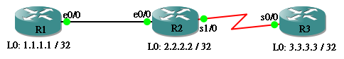
首先,R1 要到 R2 需經過 eth0/0,看看 eth0/0 的 Bandwidth 是多少?是 10000 Kbit,即是 10Mbit,cost = 100M / 10M = 10。
R1#show interfaces ether0/0 | include BW
  MTU 1500 bytes, BW 10000 Kbit, DLY 1000 usec,
然後再經過 R2 的 serial1/0,cost = 100M / 1.544M = 64。
R2#show interfaces serial 1/0 | include BW
  MTU 1500 bytes, BW 1544 Kbit, DLY 20000 usec,
到達 R3 後,還要經過 Loopback 0 這個 Interface,cost = 100M / 8000M = 1 (cost 最少值為 1)
R3#show interfaces loopback 0 | include BW
  MTU 1514 bytes, BW 8000000 Kbit, DLY 5000 usec,
因此,從 R1 要到達 R3 的 3.3.3.3,cost = 10 + 64 + 1 = 75,在 R1 的 Route Table 看看答案吧!
R1#show ip route | begin Gateway
Gateway of last resort is not set

C    192.168.12.0/24 is directly connected, Ethernet0/0
     1.0.0.0/32 is subnetted, 1 subnets
C       1.1.1.1 is directly connected, Loopback0
     2.0.0.0/32 is subnetted, 1 subnets
O       2.2.2.2 [110/11] via 192.168.12.2, 00:18:58, Ethernet0/0
     3.0.0.0/32 is subnetted, 1 subnets
O       3.3.3.3 [110/75] via 192.168.12.2, 00:18:58, Ethernet0/0
O    192.168.23.0/24 [110/74] via 192.168.12.2, 00:18:58, Ethernet0/0
相反地,從 R3 到 R1 的 1.1.1.1 應該也是 75。
R3#show ip route | begin Gateway
Gateway of last resort is not set

O    192.168.12.0/24 [110/74] via 192.168.23.2, 00:02:33, Serial0/0
     1.0.0.0/32 is subnetted, 1 subnets
O       1.1.1.1 [110/75] via 192.168.23.2, 00:02:33, Serial0/0
     2.0.0.0/32 is subnetted, 1 subnets
O       2.2.2.2 [110/65] via 192.168.23.2, 00:02:33, Serial0/0
     3.0.0.0/32 is subnetted, 1 subnets
C       3.3.3.3 is directly connected, Loopback0
C    192.168.23.0/24 is directly connected, Serial0/0
要更改 cost,有好多個方法,包括 ip ospf cost 指令、改 interface bandwidth 或者改 reference bandwidth。
ip ospf cost 指令
我們可以直接在 Interface 指定 cost 值,方法十分簡單,例如我們想設定 R1 的 eth0/0 的 cost 為 50。完成設定後 R1 到 3.3.3.3 的 metric 變成 115 了!(50 + 64 + 1 = 115)
R1(config)#int ethernet 0/0
R1(config-if)#ip ospf cost 50
R1(config-if)#end
R1#show ip route | begin Gateway
Gateway of last resort is not set

C    192.168.12.0/24 is directly connected, Ethernet0/0
     1.0.0.0/32 is subnetted, 1 subnets
C       1.1.1.1 is directly connected, Loopback0
     2.0.0.0/32 is subnetted, 1 subnets
O       2.2.2.2 [110/51] via 192.168.12.2, 00:00:08, Ethernet0/0
     3.0.0.0/32 is subnetted, 1 subnets
O       3.3.3.3 [110/115] via 192.168.12.2, 00:00:08, Ethernet0/0
O    192.168.23.0/24 [110/114] via 192.168.12.2, 00:00:08, Ethernet0/0
但必需留意的是,被更改 cost 的是 R1 的 eth0/0,從相反方向來的 Routing Metric 不會受到影響,看看 R3 的 Route Table,從 R3 到 1.1.1.1 的 Metric 是沒有改變過的。
R3#show ip route | begin Gateway
Gateway of last resort is not set

O    192.168.12.0/24 [110/74] via 192.168.23.2, 00:02:57, Serial0/0
     1.0.0.0/32 is subnetted, 1 subnets
O       1.1.1.1 [110/75] via 192.168.23.2, 00:02:58, Serial0/0
     2.0.0.0/32 is subnetted, 1 subnets
O       2.2.2.2 [110/65] via 192.168.23.2, 00:02:58, Serial0/0
     3.0.0.0/32 is subnetted, 1 subnets
C       3.3.3.3 is directly connected, Loopback0
C    192.168.23.0/24 is directly connected, Serial0/0
改 Interface Bandwidth
由於 cost = 100M / Interface Bandwidth,所以我們可以更改 Interface Bandwidth 達到設定 cost 的效果,例如:我們想把 R1 E0/0 cost 設定為 20 的話,可以把 Interface Bandwidth 調到 5M。如下圖,修改 bandwidth 後,metric 變成 85。(20 + 64 + 1 = 85) 請留意,修改 Bandwidth 只會對 Routing Protocol 計算 cost 時造成影響,並不會直正改變 Interface 的傳輸速度。
R1(config)#int ethernet 0/0
R1(config-if)#bandwidth ?
  <1-10000000>  Bandwidth in kilobits
  inherit       Specify that bandwidth is inherited
  receive       Specify receive-side bandwidth

R1(config-if)#bandwidth 5000
R1(config-if)#end
R1#
R1#show ip route | begin Gateway
Gateway of last resort is not set

C    192.168.12.0/24 is directly connected, Ethernet0/0
     1.0.0.0/32 is subnetted, 1 subnets
C       1.1.1.1 is directly connected, Loopback0
     2.0.0.0/32 is subnetted, 1 subnets
O       2.2.2.2 [110/21] via 192.168.12.2, 00:00:13, Ethernet0/0
     3.0.0.0/32 is subnetted, 1 subnets
O       3.3.3.3 [110/85] via 192.168.12.2, 00:00:13, Ethernet0/0
O    192.168.23.0/24 [110/84] via 192.168.12.2, 00:00:13, Ethernet0/0
改 reference bandwidth
最後一招是更改 reference bandwidth,同樣地 cost 會因而改變,現在試試把 reference bandwidth 改成 1000,看看會出現什麼狀況。Metric 變成 165,因為 R1 eth0/0 的 cost 變成 1000/10 = 100,cost 的總和等於 100 + 64 + 1 = 165。雖然並非必要,但如果要更改 reference bandwidth 的話,請在所有 OSPF Router 都一併更改,否則各 Router 會出現 Bandwidth 相同而 cost 不同的情況,對 troubleshooting 造成障礙。
R1(config)#router ospf 1
R1(config-router)#auto-cost reference-bandwidth 1000
R1(config-router)#end
R1#show ip route | begin Gateway
Gateway of last resort is not set

C    192.168.12.0/24 is directly connected, Ethernet0/0
     1.0.0.0/32 is subnetted, 1 subnets
C       1.1.1.1 is directly connected, Loopback0
     2.0.0.0/32 is subnetted, 1 subnets
O       2.2.2.2 [110/101] via 192.168.12.2, 00:01:46, Ethernet0/0
     3.0.0.0/32 is subnetted, 1 subnets
O       3.3.3.3 [110/165] via 192.168.12.2, 00:01:46, Ethernet0/0
O    192.168.23.0/24 [110/164] via 192.168.12.2, 00:01:46, Ethernet0/0
補充一點,如果網絡裡有超過 100M 的 Interface 的話,請慕必要加大 Reference Bandwidth,因為在預設 100M 的情況下,10G、1G 和 100M Interface 計算出來的 cost 都會是 1 (因最少值為1),這就無法讓 OSPF 準確判斷 link 的快慢了。
改 Neighbor Cost
如果 Network Type 是 Point-to-Multipoint Non Broadcast 的話,可以直接更改 Neighbor Cost,這樣做可以設定對方傳來的 Route 的 Cost。但這個方法比較少用。
R7(config)#int serial 0/0
R7(config-if)#ip ospf network point-to-multipoint non-broadcast
R7(config-if)#end
R7(config)#router ospf 1
R7(config-router)#neighbor 192.168.23.2 cost 999
External Route Cost
不知道大家還有沒有印像,在較早前有提及過 External Route 可以分為 E1 或者 E2,究竟有什麽分別呢?現在來為大家解開這個疑團。我們將會把以下網絡中的 EIGRP Redistribute 到 OSPF 中。
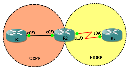
首先我們試試把 External Route Type 設成 E1,把 Metric 設定成 99。
hostname R2
!
router eigrp 100
 network 192.168.23.0
 no auto-summary
!
router ospf 1
 redistribute eigrp 100 metric-type 1 metric 99
 network 192.168.12.0 0.0.0.255 area 0
到 R1 看看 Route Table,External Route 有標明 E1,而 Metric 是 109,即是把 R1 到 R2 的 10 加上 redistribute 的 metric 99,總和是 109,很不錯!
R1#show ip route | begin Gateway
Gateway of last resort is not set

C    192.168.12.0/24 is directly connected, Ethernet0/0
     1.0.0.0/32 is subnetted, 1 subnets
C       1.1.1.1 is directly connected, Loopback0
O E1 192.168.23.0/24 [110/109] via 192.168.12.2, 00:00:10, Ethernet0/0
如果使用 Metric Type 2 就會變成怎樣呢?
hostname R2
!
router eigrp 100
 network 192.168.23.0
 no auto-summary
!
router ospf 1
 redistribute eigrp 100 metric-type 2 metric 99
 network 192.168.12.0 0.0.0.255 area 0
發現 E2 只使用了 External Route 的 Metric 99,原來 E2 只會使用 External Route 的 Metric 而不會加入 OSPF Router 的 Cost。留意如果不使用 metric-type 參數的話,預設會使用 E2 的。
R1#show ip route | begin Gateway
Gateway of last resort is not set

C    192.168.12.0/24 is directly connected, Ethernet0/0
     1.0.0.0/32 is subnetted, 1 subnets
C       1.1.1.1 is directly connected, Loopback0
O E2 192.168.23.0/24 [110/99] via 192.168.12.2, 00:00:18, Ethernet0/0
路徑選擇
跟其他 Routing Protocol 一樣,OSPF 並不會把全部路徑都放進 Route Table,只會選擇當中一條或多條路徑。究竟 OSPF 選擇路徑的邏輯是怎樣呢?當有多條路徑能夠抵達目的地,OSPF 會按以下順序來選擇:
- 先按 Route Type 來選擇:Intra-area (O) > Inter-area (O IA) > Type 1 Exteranl (O E1 / N1) > Type 2 External (O E2 / N2)
- 如果 Route Type 相同,比較 Metric,較小者獲勝
- 如果 Metric 相同,選擇 n 條 path 一併加進 Route Table,進行 load balancing (n = maximum-paths 參數)
Route Type
看過筆者的文章你都知道,不是書本說什麽我就相信,當然又來做個實驗去證實一下啦!
這個實驗設定頗為複雜,目的在於為 R1 同時提供四條能夠到達 6.6.6.6 而 Metric 相同的 Route,分別是:
- 經 R5 的 Intra-area Route (O)
- 經 R4 的 Inter-area Route (O IA)
- 經 R3 的 E1 External Route (O E1)
- 經 R2 的 E2 External Route (O E2)
各 Router 設定如下:
hostname R1
!
interface Loopback0
 ip address 1.1.1.1 255.255.255.255
!
interface Ethernet0/0
 ip address 192.168.12.1 255.255.255.0
!
interface Ethernet0/1
 ip address 192.168.13.1 255.255.255.0
!
interface Ethernet0/2
 ip address 192.168.14.1 255.255.255.0
!
interface Ethernet0/3
 ip address 192.168.15.1 255.255.255.0
!
router ospf 1
 network 192.168.12.0 0.0.0.255 area 0
 network 192.168.13.0 0.0.0.255 area 0
 network 192.168.14.0 0.0.0.255 area 0
 network 192.168.15.0 0.0.0.255 area 10
hostname R2
!
interface Loopback0
 ip address 2.2.2.2 255.255.255.255
!
interface Ethernet0/0
 ip address 192.168.12.2 255.255.255.0
!
interface Ethernet0/1
 ip address 192.168.26.2 255.255.255.0
!
router eigrp 100
 network 192.168.26.0
 no auto-summary
!
router ospf 1
 redistribute eigrp 100 metric 21 subnets
 network 192.168.12.0 0.0.0.255 area 0
hostname R3
!
interface Loopback0
 ip address 3.3.3.3 255.255.255.255
!
interface Ethernet0/0
 ip address 192.168.13.3 255.255.255.0
!
interface Ethernet0/1
 ip address 192.168.36.3 255.255.255.0
!
router eigrp 200
 network 192.168.36.0
 no auto-summary
!
router ospf 1
 redistribute eigrp 200 metric 11 metric-type 1 subnets
 network 192.168.13.0 0.0.0.255 area 0
hostname R4
!
interface Loopback0
 ip address 4.4.4.4 255.255.255.255
!
interface Ethernet0/0
 ip address 192.168.14.4 255.255.255.0
!
interface Ethernet0/1
 ip address 192.168.46.4 255.255.255.0
!
router ospf 1
 network 192.168.14.0 0.0.0.255 area 0
 network 192.168.46.0 0.0.0.255 area 10
hostname R5
!
interface Loopback0
 ip address 5.5.5.5 255.255.255.255
!
interface Ethernet0/0
 ip address 192.168.15.5 255.255.255.0
!
interface Ethernet0/1
 ip address 192.168.56.5 255.255.255.0
!
router ospf 1
 network 192.168.15.0 0.0.0.255 area 10
 network 192.168.56.0 0.0.0.255 area 10
hostname R6
!
interface Loopback0
 ip address 6.6.6.6 255.255.255.255
!
interface Ethernet0/0
 ip address 192.168.26.6 255.255.255.0
!
interface Ethernet0/1
 ip address 192.168.36.6 255.255.255.0
!
interface Ethernet0/2
 ip address 192.168.46.6 255.255.255.0
 half-duplex
!
interface Ethernet0/3
 ip address 192.168.56.6 255.255.255.0
!
router eigrp 100
 network 6.6.6.6 0.0.0.0
 network 192.168.26.0
 no auto-summary
!
router eigrp 200
 network 6.6.6.6 0.0.0.0
 network 192.168.36.0
 no auto-summary
!
router ospf 1
 network 6.6.6.6 0.0.0.0 area 10
 network 192.168.46.0 0.0.0.255 area 10
 network 192.168.56.0 0.0.0.255 area 10
實驗開始時,我們先把 R1 的 eth0/1、eth0/2、eth0/3 關掉,這樣 R1 就只有 Next Hop R2 (192.168.12.2) 這條 E2 路徑到達 6.6.6.6,結果正常。
R1(config)#interface range ethernet 0/1 - 3
R1(config-if-range)#shutdown
R1(config-if-range)#end
R1#
R1#show ip route | include 6.6.6.6
O E2    6.6.6.6 [110/21] via 192.168.12.2, 00:14:35, Ethernet0/0
現在我們把 eth0/1 打開,由於 Next Hop R3 (192.168.13.3) 這條 Route 是 E1,OSPF 認為 E1 比 E2 好,所以就選了 E1 放入 Route Table,代替了 E2。
R1(config)#interface ethernet 0/1
R1(config-if)#no shutdown
R1(config-if)#end
R1
R1#show ip route | include 6.6.6.6
O E1    6.6.6.6 [110/21] via 192.168.13.3, 00:00:46, Ethernet0/1
接著,再把 eth0/2 打開,Next Hop R4 (192.168.14.4) 是 O IA Route,又比 E1 好,所以 OSPF 選擇了這條 Route。
R1(config)#interface ethernet 0/2
R1(config-if)#no shutdown
R1(config-if)#end
R1#
R1#show ip route | include 6.6.6.6
O IA    6.6.6.6 [110/21] via 192.168.14.4, 00:00:05, Ethernet0/2
最後,把 eth0/3 打開,當然 R1 會選 Next Hop 為 R5 (192.168.15.5) 因為 Intra-area route 你是最好的!
R1(config)#interface ethernet 0/3
R1(config-if)#no shutdown
R1(config-if)#end
R1#
R1#show ip route | include 6.6.6.6
O       6.6.6.6 [110/21] via 192.168.15.5, 00:00:00, Ethernet0/3
比較 Metric
如果在同一個 Route Type 之下,OSPF 會選 Metric 較少的放進 Route Table ,這個實驗就簡單得多了。只需要把以下網絡全部 Interface 放進同一個 Area 之中,這樣,全部路徑都會是 Intra-area Route,然後在 R1 把 Interface 設定成不同 Cost,再看看 Route Table 即可得到答案。
這時候,R2 的路徑 Metric 為 30 + 10 + 1 = 41,R3 的路徑 Metric 為 20 + 10 + 1 = 31,而 R4 的路徑 Metric 為 10 + 10 + 1 = 21,當然會選擇 Metric 最少的 R4 路徑了。
R1(config)#interface ethernet 0/0
R1(config-if)#ip ospf cost 30
R1(config-if)#interface ethernet 0/1
R1(config-if)#ip ospf cost 20
R1(config-if)#interface ethernet 0/2
R1(config-if)#ip ospf cost 10
R1
R1#show ip route | include 5.5.5.5
O       5.5.5.5 [110/21] via 192.168.14.4, 00:00:03, Ethernet0/2
Load Balancing
如果 Route Type 和 Metric 都不能分出勝負,在 Metric 相同的情況下,OSPF 預設最多會選 4 條 Route 放進 Route Table,進行 Load Balancing。再用上一個例子的網絡為例,如果 R1 的三個 Interface 的 Cost 全部相同,三條 Route 都被放進 Route Table 去。
R1#show ip ospf interface ethernet 0/0 | include Cost
  Process ID 1, Router ID 192.168.114.1, Network Type BROADCAST, Cost: 10
R1#show ip ospf interface ethernet 0/1 | include Cost
  Process ID 1, Router ID 192.168.114.1, Network Type BROADCAST, Cost: 10
R1#show ip ospf interface ethernet 0/2 | include Cost
  Process ID 1, Router ID 192.168.114.1, Network Type BROADCAST, Cost: 10
R1
R1#show ip route | begin 5.5.5.5
O       5.5.5.5 [110/21] via 192.168.14.4, 00:00:54, Ethernet0/2
                [110/21] via 192.168.13.3, 00:00:54, Ethernet0/1
                [110/21] via 192.168.12.2, 00:00:54, Ethernet0/0
O    192.168.35.0/24 [110/20] via 192.168.13.3, 00:00:54, Ethernet0/1
OSPF 的預設 4 條 Load Balance 是可以修改的,只要在 OSPF 設定下用指令 maximum-paths <no of path> 便可以設定 1 至 16 條 Load Balance Route。例如,把 R1 改成 maximum-paths 2 會怎樣呢?Route Table 變成只有 2 條 Load Balance Route 了。
R1(config)#router ospf 1
R1(config-router)#maximum-paths ?
  <1-16>  Number of paths

R1(config-router)#maximum-paths 2
R1(config-router)#end
R1#
R1#show ip route | begin 5.5.5.5
O       5.5.5.5 [110/21] via 192.168.13.3, 00:00:13, Ethernet0/1
                [110/21] via 192.168.12.2, 00:00:13, Ethernet0/0
O    192.168.35.0/24 [110/20] via 192.168.13.3, 00:00:13, Ethernet0/1
甚至試試改成 1 會怎樣,變成只有 1 條了。可惜的是,筆者找了很久,也不知道 OSPF 究竟按什麼次序去從 3 條相同 Metric 的 Route 中選擇 1 條,如果各位網友找到答案的話,請幫忙留個言。
R1(config)#router ospf 1
R1(config-router)#maximum-paths 1
R1(config-router)#end
R1#
R1#show ip route | begin 5.5.5.5
O       5.5.5.5 [110/21] via 192.168.12.2, 00:00:03, Ethernet0/0
O    192.168.35.0/24 [110/20] via 192.168.13.3, 00:00:03, Ethernet0/1
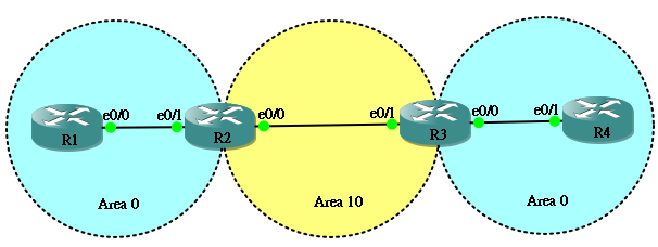
Virtual Link
Virtual Link 的概念非常簡單,就是把兩個實體上分離的 Area 相連起來。一般有兩個用途,它可以幫沒有直接連著 Backbone Area 0 的 Area 建立一條 Virtual Link 連接起來;另外,它也可以把「斷開」的 Area 0 接駁起來。
接駁至 Area 0
在文章初段已經說明過,所有 Area 必需連接 Backbone Area 0。
以上圖為例,Area 20 沒有實體連線至 Area 0,就算把所有 OSPF 的設定做好了,R1 與 R2 都不會收到 Area 20 的 Route。
R1#show ip route | begin Gateway
Gateway of last resort is not set

C    192.168.12.0/24 is directly connected, Ethernet0/0
     1.0.0.0/32 is subnetted, 1 subnets
C       1.1.1.1 is directly connected, Loopback0
O IA 192.168.23.0/24 [110/20] via 192.168.12.2, 00:15:19, Ethernet0/0
R2#show ip route | begin Gateway
Gateway of last resort is not set

C    192.168.12.0/24 is directly connected, Ethernet0/1
     2.0.0.0/32 is subnetted, 1 subnets
C       2.2.2.2 is directly connected, Loopback0
C    192.168.23.0/24 is directly connected, Ethernet0/0
然後,我們在 R2 和 R3 用 area <transit area> virtual-link <router-id> 指令來設定 virtual link。Transit area 是 virtual link 所經過的 Area,而 router-id 則是對方的 Router ID。
R2(config)#router ospf 1
R2(config-router)#area 10 virtual-link 3.3.3.3
R3(config)#router ospf 1
R3(config-router)#area 10 virtual-link 2.2.2.2
於是 R1 和 R2 都收到 Area 20 的 Route 了。
R1#show ip route | begin Gateway
Gateway of last resort is not set

C    192.168.12.0/24 is directly connected, Ethernet0/0
     1.0.0.0/32 is subnetted, 1 subnets
C       1.1.1.1 is directly connected, Loopback0
O IA 192.168.23.0/24 [110/20] via 192.168.12.2, 00:01:06, Ethernet0/0
O IA 192.168.34.0/24 [110/30] via 192.168.12.2, 00:01:06, Ethernet0/0
R2#show ip route | begin Gateway
Gateway of last resort is not set

C    192.168.12.0/24 is directly connected, Ethernet0/1
     2.0.0.0/32 is subnetted, 1 subnets
C       2.2.2.2 is directly connected, Loopback0
C    192.168.23.0/24 is directly connected, Ethernet0/0
O IA 192.168.34.0/24 [110/20] via 192.168.23.3, 00:01:40, Ethernet0/0
接駁兩個 Area 0
由於整個 OSPF 網絡中只可存在一個 Backbone Area 0,如果有兩個 Area 0 的話,必需用 Virtual Link 將其相連起來。
按上圖的設定,在沒有設定 Virtual Link 的情況下,兩個 Area 0 沒法相連。
R1#show ip route | begin Gateway
Gateway of last resort is not set

C    192.168.12.0/24 is directly connected, Ethernet0/0
     1.0.0.0/32 is subnetted, 1 subnets
C       1.1.1.1 is directly connected, Loopback0
O IA 192.168.23.0/24 [110/20] via 192.168.12.2, 00:03:36, Ethernet0/0
R4#show ip route | begin Gateway
Gateway of last resort is not set

     4.0.0.0/32 is subnetted, 1 subnets
C       4.4.4.4 is directly connected, Loopback0
O IA 192.168.23.0/24 [110/20] via 192.168.34.3, 00:03:45, Ethernet0/1
C    192.168.34.0/24 is directly connected, Ethernet0/1
所以要在 R2 和 R3 之間建立 Virtual Link。
R2(config)#router ospf 1
R2(config-router)#area 10 virtual-link 3.3.3.3
R3(config)#router ospf 1
R3(config-router)#area 10 virtual-link 2.2.2.2
兩個 Area 0 互相看到大家了,留意一點,雖然經過了 Area 10,但這條 Area 0 去 Area 0 的 Route 依然被視為 Intra-area Route。
R1#show ip route | begin Gateway
Gateway of last resort is not set

C    192.168.12.0/24 is directly connected, Ethernet0/0
     1.0.0.0/32 is subnetted, 1 subnets
C       1.1.1.1 is directly connected, Loopback0
O IA 192.168.23.0/24 [110/20] via 192.168.12.2, 00:00:54, Ethernet0/0
O    192.168.34.0/24 [110/30] via 192.168.12.2, 00:00:54, Ethernet0/0
R4#show ip route | begin Gateway
Gateway of last resort is not set

O    192.168.12.0/24 [110/30] via 192.168.34.3, 00:01:09, Ethernet0/1
     4.0.0.0/32 is subnetted, 1 subnets
C       4.4.4.4 is directly connected, Loopback0
O IA 192.168.23.0/24 [110/20] via 192.168.34.3, 00:01:09, Ethernet0/1
C    192.168.34.0/24 is directly connected, Ethernet0/1
Summarization
Summarization 可以把相連的 Network 組合起來,有效減少 Route 的數量。OSPF 的 Summarization 指令有兩款,一款是用在 ABR 的 Area Range,而另一款則是用在 ASBR 的 Summary Address。用以下網絡做例子,ABR R2 會把 172.16.0.1/32 及 172.16.1.1/32 兩個 Network Summary,而 ASBR R3 則會把 172.16.2.1/32 及 172.16.3.1/32 Redistribute 到 OSPF 之中,並把它們 Summary。
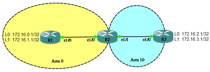
Area Range
在執行 Summary 之前,先在 R3 看看 Route Table,正分別收到 172.16.0.1/32 及 172.16.1.1/32 兩條 Route。
R3#show ip route ospf
Codes: L - local, C - connected, S - static, R - RIP, M - mobile, B - BGP
       D - EIGRP, EX - EIGRP external, O - OSPF, IA - OSPF inter area
       N1 - OSPF NSSA external type 1, N2 - OSPF NSSA external type 2
       E1 - OSPF external type 1, E2 - OSPF external type 2
       i - IS-IS, su - IS-IS summary, L1 - IS-IS level-1, L2 - IS-IS level-2
       ia - IS-IS inter area, * - candidate default, U - per-user static route
       o - ODR, P - periodic downloaded static route, H - NHRP, l - LISP
       + - replicated route, % - next hop override

Gateway of last resort is not set

      172.16.0.0/32 is subnetted, 4 subnets
O IA     172.16.0.1 [110/21] via 192.168.23.2, 00:09:51, Ethernet1/0
O IA     172.16.1.1 [110/21] via 192.168.23.2, 00:09:51, Ethernet1/0
O IA  192.168.12.0/24 [110/20] via 192.168.23.2, 00:09:51, Ethernet1/0
在 R2 下 Area Range 指令:
R2(config)#router ospf 1
R2(config-router)#area 0 range 172.16.0.0 255.255.254.0。
這樣 R3 只會收到 Summary Route 172.16.0.0/23
R3#show ip route ospf
Codes: L - local, C - connected, S - static, R - RIP, M - mobile, B - BGP
       D - EIGRP, EX - EIGRP external, O - OSPF, IA - OSPF inter area
       N1 - OSPF NSSA external type 1, N2 - OSPF NSSA external type 2
       E1 - OSPF external type 1, E2 - OSPF external type 2
       i - IS-IS, su - IS-IS summary, L1 - IS-IS level-1, L2 - IS-IS level-2
       ia - IS-IS inter area, * - candidate default, U - per-user static route
       o - ODR, P - periodic downloaded static route, H - NHRP, l - LISP
       + - replicated route, % - next hop override

Gateway of last resort is not set

      172.16.0.0/16 is variably subnetted, 3 subnets, 2 masks
O IA     172.16.0.0/23 [110/21] via 192.168.23.2, 00:02:02, Ethernet1/0
O IA  192.168.12.0/24 [110/20] via 192.168.23.2, 00:17:06, Ethernet1/0
Summary Address
R3 把 172.16.2.1/32 及 172.16.3.1/32 Redistribute 到 OSPF 使其成為 ASBR,在 R1 看 Route Table 會看到這兩條 External Route。
R1#show ip route ospf
Codes: L - local, C - connected, S - static, R - RIP, M - mobile, B - BGP
       D - EIGRP, EX - EIGRP external, O - OSPF, IA - OSPF inter area
       N1 - OSPF NSSA external type 1, N2 - OSPF NSSA external type 2
       E1 - OSPF external type 1, E2 - OSPF external type 2
       i - IS-IS, su - IS-IS summary, L1 - IS-IS level-1, L2 - IS-IS level-2
       ia - IS-IS inter area, * - candidate default, U - per-user static route
       o - ODR, P - periodic downloaded static route, H - NHRP, l - LISP
       + - replicated route, % - next hop override

Gateway of last resort is not set

      172.16.0.0/32 is subnetted, 4 subnets
O E2     172.16.2.1 [110/20] via 192.168.12.2, 00:00:09, Ethernet1/0
O E2     172.16.3.1 [110/20] via 192.168.12.2, 00:00:03, Ethernet1/0
O IA  192.168.23.0/24 [110/20] via 192.168.12.2, 00:21:24, Ethernet1/0
現在於 R3 下 Summary Address 指令把兩條 External Route 組起來。
R3(config)#router ospf 1
R3(config-router)#summary-address 172.16.2.0 255.255.254.0
於是 R1 收到一條已被 Summary 的 External Route。
R1#show ip route ospf
Codes: L - local, C - connected, S - static, R - RIP, M - mobile, B - BGP
       D - EIGRP, EX - EIGRP external, O - OSPF, IA - OSPF inter area
       N1 - OSPF NSSA external type 1, N2 - OSPF NSSA external type 2
       E1 - OSPF external type 1, E2 - OSPF external type 2
       i - IS-IS, su - IS-IS summary, L1 - IS-IS level-1, L2 - IS-IS level-2
       ia - IS-IS inter area, * - candidate default, U - per-user static route
       o - ODR, P - periodic downloaded static route, H - NHRP, l - LISP
       + - replicated route, % - next hop override

Gateway of last resort is not set

      172.16.0.0/16 is variably subnetted, 3 subnets, 2 masks
O E2     172.16.2.0/23 [110/20] via 192.168.12.2, 00:00:31, Ethernet1/0
O IA  192.168.23.0/24 [110/20] via 192.168.12.2, 00:23:40, Ethernet1/0
No discard-route
無論 ABR 或 ASBR 做 Summary 時都會自動產生一條指向 Null0 的 Route,目的是把 Summary Network 裡找不到目的地的 Packet Discard 掉,避免產生 Route Loop。
R2#show ip route ospf
Codes: L - local, C - connected, S - static, R - RIP, M - mobile, B - BGP
       D - EIGRP, EX - EIGRP external, O - OSPF, IA - OSPF inter area
       N1 - OSPF NSSA external type 1, N2 - OSPF NSSA external type 2
       E1 - OSPF external type 1, E2 - OSPF external type 2
       i - IS-IS, su - IS-IS summary, L1 - IS-IS level-1, L2 - IS-IS level-2
       ia - IS-IS inter area, * - candidate default, U - per-user static route
       o - ODR, P - periodic downloaded static route, H - NHRP, l - LISP
       + - replicated route, % - next hop override

Gateway of last resort is not set

      172.16.0.0/16 is variably subnetted, 3 subnets, 2 masks
O        172.16.0.0/23 is a summary, 00:13:10, Null0
O        172.16.1.1/32 [110/11] via 192.168.12.1, 00:13:10, Ethernet1/0
O E2     172.16.2.0/23 [110/20] via 192.168.23.3, 00:05:31, Ethernet1/1
如果想在 ABR 移除這條 Route 的話可以用 no discard-route internal 指令,但必需小心,確定不會造成 Routing Loop 才可執行。
R2(config)#router ospf 1
R2(config-router)#no discard-route internal
如想移除由 ASBR Summary 所產生的 Null0 Route,則用 no discard-route external 指令。
OSPF 優化
Pacing Timer
OSPF 每隔 1,800 秒就會把 Link State 重新發佈,在 OSPF Database 裡可以看到 Link State 的 Age,所以,理論上當 Age 數到 1,800 就要重新發佈。但當 Link State 很多的時候,這樣一條一條處理變得很無效率,很耗 CPU。因此,OSPF 會把多條發佈時間相約的 Link State 一起處理,用 Group Pacing Timer 來控制。例如:OSPF 預設 Group Pacing Timer 為 240 秒,即是說當有 Link State 的 Age 數到 1,800 秒也不要立刻處理,先等一下,等多久?等 240 秒,如果在這 240 秒期間還有其他 Link State 到期的話,就一同安排發佈。如要修改 Group Pacing Timer 可用 timers pacing lsa-group 指令。
R2(config)#router ospf 1
R2(config-router)#timers pacing lsa-group 500
然後,需要重發的 Link State 會被放進 Interface 的 LSA Flood List 準備送出,但把 LSA 一個一個的送出又造成很大的 Overhead,所以又有一個叫 Interface flood pacing timer,預設為 33 msecs,意思是等待 33 msecs 才發出一個 Update Packet,每個 Packet 就可以包含多條 LSA。修改 Interface flood pacing timer 的指令為 timers pacing flood。
R2(config)#router ospf 1
R2(config-router)#timers pacing flood 50
發出 LSA 後,對方應該回傳 ACK 表示收到該 LSA,如收不到對方回應 ACK 則需重發 LSA。同一道理,Retransmission pacing timer 控制 Retransmission Packet 的等待時間。修改 Retransmission pacing timer 的指令為 timers pacing retransmission。
R2(config)#router ospf 1
R2(config-router)#timers pacing retransmission 100
用 show ip ospf 可看到 timer 設定值。
R2#show ip ospf | i pacing
 LSA group pacing timer 500 secs
 Interface flood pacing timer 50 msecs
 Retransmission pacing timer 100 msecs
SPF Throttle Timer
另一組優化 OSPF 的 Timer 稱為 SPF Throttle Timer。OSPF 是透過 SPF 來計算出路徑,SPF 是消耗 CPU 的程序,如每次收到 Link State 狀態改變 (或稱 Event) 都立刻進行 SPF 運算會對 Router 造成資源衝擊,另一狀況是如果有 Link 出現持斷的 Up Down (即 Flapping),不斷轉變 Topology 會對網絡造成不穩定。因此,OSPF Router 收到 Event 後,會先等待相等於 hold-time 的時間,在這段時間內收到的 Event 會被收集在一起進行 SPF 運算,hold-time 起始值為 Initial SPF schedule delay,或稱 Initial (預設值為 5,000 msecs)。
如 Event 不斷出現,hold-time 會不斷增加,當第一波的 Event 被處理後,hold-time 會變成相等於 Minimum hold time between two consecutive SPFs 的值,或稱 Increment (預設為 10,000 msecs),延長 hold-time 是為了應付第二波可能出現更多的 Event,減少 SPF 運算次數。
如第二波 hold-time 仍有 Event 出現,hold-time 會再被倍增至 2 x Increment 應付第三波。如第三波仍有 Event 出現,hold-time 會再被倍增至 4 x Increment,如此類推。
然而,hold-time 並不會無止境地增長,當 hold-time 到達 Maximum wait time between two consecutive SPFs (或稱 Max Wait) 就會停止增長。如連續兩次 hold-time 都沒有再收到 Event,網絡似乎穩定下來了,hold-time 就被重新設定成 Initial SPF schedule delay。
設定 SPF Throttle Timer 的指令為 timers throttle spf <initial> <increment> <max wait>。
R2(config)#router ospf 1
R2(config-router)#timers throttle spf 10000 20000 100000
R2(config-router)#end
R2#show ip ospf | i SPF
 Initial SPF schedule delay 10000 msecs
 Minimum hold time between two consecutive SPFs 20000 msecs
 Maximum wait time between two consecutive SPFs 100000 msecs
 <--Output Omitted-->
LSA Throttle Timer
由 OSPF Router 因為 Local Link 狀態改變而所產生的 LSA 受 LSA Throttle Timer 所影響,原理就和 SPF Throttle Timer 控制 SPF 運算一樣,設定 LSA Timer 的指令為 timers throttle lsa <initial> <increment> <max wait>。
R2(config)#router ospf 1
R2(config-router)#timers throttle lsa 20000 30000 50000
R2(config-router)#end
R2#show ip ospf | i LSA | i msecs
 Initial LSA throttle delay 20000 msecs
 Minimum hold time for LSA throttle 30000 msecs
 Maximum wait time for LSA throttle 50000 msecs
 <--Output Omitted-->
相關主題
Jan Ho 2014-01-25
Posted In: Layer 3 網絡技術, menu-tall-3-zh-hant
發佈留言