目錄
前言
當一個 Packet 從一個 Incoming Interface 到達 Router,Router 如何處理呢?當然它希望盡快把 Packet 放到適當的 Outgoing Interface 送出去。不過 Router 可能同時接駁著多個 Interface,所以 Router 需要查看自己的 Route Table 去決定把 Packet 放到那一個 Interface 送走。本篇文章會剖析 Router 所謂的 Route Decision 流程,並講解一些基本的 Static Route 設定。
Route Table
當一個 Packet 到達,Router 會立刻檢查 Packet 的 Layer 3 Destination Address (即 Destination IP),然後在 Route Table 中找出一條最適合的紀錄,依據紀錄,把 Packet 放到對應的 Interface 送走,這就是 Router 每分每秒的工作了。要查看 Route Table,可以用一個極常用的指令:show ip route。
以下是一個 Route Table 的例子:
R1#show ip route
Codes: C - connected, S - static, R - RIP, M - mobile, B - BGP
       D - EIGRP, EX - EIGRP external, O - OSPF, IA - OSPF inter area
       N1 - OSPF NSSA external type 1, N2 - OSPF NSSA external type 2
       E1 - OSPF external type 1, E2 - OSPF external type 2
       i - IS-IS, su - IS-IS summary, L1 - IS-IS level-1, L2 - IS-IS level-2
       ia - IS-IS inter area, * - candidate default, U - per-user static route
       o - ODR, P - periodic downloaded static route

Gateway of last resort is not set

C    192.168.12.0/24 is directly connected, Ethernet0/0
     2.0.0.0/32 is subnetted, 1 subnets
S       2.2.2.2 [1/0] via 192.168.30.1, Ethernet0/0
                is directly connected, Ethernet0/0
     192.168.1.0/24 is variably subnetted, 4 subnets, 4 masks
S       192.168.1.32/29 [1/0] via 192.168.12.12
S       192.168.1.32/28 [1/0] via 192.168.12.12
S       192.168.1.0/26 [1/0] via 192.168.12.11
S       192.168.1.0/24 [1/0] via 192.168.12.2
D    192.168.2.0/23 [90/409600] via 192.168.12.2, 01:21:55, Ethernet0/0
Route Table 的來源
那麽 Route Table 的紀錄是從那裡來呢?Router 其本上會用從以下三個來源去建立自己的 Route Table。
1. Interface Network
Router 會收集每一個使用中的 Interface,如果有設 IP 的話,這個 Network 就會被放進 Route Table。以下是一個例子,在 R1 上的 Route Table 原本是空空的。
R1#show ip route
Codes: C - connected, S - static, R - RIP, M - mobile, B - BGP
       D - EIGRP, EX - EIGRP external, O - OSPF, IA - OSPF inter area
       N1 - OSPF NSSA external type 1, N2 - OSPF NSSA external type 2
       E1 - OSPF external type 1, E2 - OSPF external type 2
       i - IS-IS, su - IS-IS summary, L1 - IS-IS level-1, L2 - IS-IS level-2
       ia - IS-IS inter area, * - candidate default, U - per-user static route
       o - ODR, P - periodic downloaded static route

Gateway of last resort is not set
然後我們在 Interface 設定 IP Address 並把 Interface 啟動 (假設這個 Interface 所連接的另一端已經啟動了),這時再看看 Route Table 就發現多了一條 Route。
R1#configure terminal
Enter configuration commands, one per line.  End with CNTL/Z.
R1(config)#int ethernet 0/0
R1(config-if)#ip address 192.168.12.1 255.255.255.0
R1(config-if)#no shutdown
R1#show ip route
Codes: C - connected, S - static, R - RIP, M - mobile, B - BGP
       D - EIGRP, EX - EIGRP external, O - OSPF, IA - OSPF inter area
       N1 - OSPF NSSA external type 1, N2 - OSPF NSSA external type 2
       E1 - OSPF external type 1, E2 - OSPF external type 2
       i - IS-IS, su - IS-IS summary, L1 - IS-IS level-1, L2 - IS-IS level-2
       ia - IS-IS inter area, * - candidate default, U - per-user static route
       o - ODR, P - periodic downloaded static route

Gateway of last resort is not set

C    192.168.12.0/24 is directly connected, Ethernet0/0
2. Static Route
如果 Router Configuration 中有設 Static Route 的話,也會被放進 Route Table。以下我們試加一條 Static Route。
R1#configure terminal
Enter configuration commands, one per line.  End with CNTL/Z.
R1(config)#ip route 192.168.1.0 255.255.255.0 192.168.12.2
R1(config)#end
R1#show ip route
Codes: C - connected, S - static, R - RIP, M - mobile, B - BGP
       D - EIGRP, EX - EIGRP external, O - OSPF, IA - OSPF inter area
       N1 - OSPF NSSA external type 1, N2 - OSPF NSSA external type 2
       E1 - OSPF external type 1, E2 - OSPF external type 2
       i - IS-IS, su - IS-IS summary, L1 - IS-IS level-1, L2 - IS-IS level-2
       ia - IS-IS inter area, * - candidate default, U - per-user static route
       o - ODR, P - periodic downloaded static route

Gateway of last resort is not set

C    192.168.12.0/24 is directly connected, Ethernet0/0
S    192.168.1.0/24 [1/0] via 192.168.12.2
3. Dynamic Routing Protocol
如果 Router 有設 Dynamic Routing Protocol,Router 與 Router 之間就會交換 Route 資訊,Dynamic Routing Protocol 會對這些資訊進行運算,最後把結果放進 Route Table。現在我們試試在 Router 上設定 EIGRP,假設 Interface 另一端的 Router 已經設好了 EIGRP。完成設定後便可看到由 Dynamic Routing Protocol 產生的 Route。
R1(config)#router eigrp 1
R1(config-router)#network 192.168.12.0
R1#show ip route
Codes: C - connected, S - static, R - RIP, M - mobile, B - BGP
       D - EIGRP, EX - EIGRP external, O - OSPF, IA - OSPF inter area
       N1 - OSPF NSSA external type 1, N2 - OSPF NSSA external type 2
       E1 - OSPF external type 1, E2 - OSPF external type 2
       i - IS-IS, su - IS-IS summary, L1 - IS-IS level-1, L2 - IS-IS level-2
       ia - IS-IS inter area, * - candidate default, U - per-user static route
       o - ODR, P - periodic downloaded static route

Gateway of last resort is not set

C    192.168.12.0/24 is directly connected, Ethernet0/0
S    192.168.1.0/24 [1/0] via 192.168.12.2
D    192.168.2.0/24 [90/409600] via 192.168.12.2, 00:01:31, Ethernet0/0
Route Table 解說
每條 Route 都包含幾項資訊,我們用最後的一條由 EIGRP 所產生的 Route 作例子,解釋如下:
R1(config)#router eigrp 1
R1#show ip route
Codes: C - connected, S - static, R - RIP, M - mobile, B - BGP
       D - EIGRP, EX - EIGRP external, O - OSPF, IA - OSPF inter area
       N1 - OSPF NSSA external type 1, N2 - OSPF NSSA external type 2
       E1 - OSPF external type 1, E2 - OSPF external type 2
       i - IS-IS, su - IS-IS summary, L1 - IS-IS level-1, L2 - IS-IS level-2
       ia - IS-IS inter area, * - candidate default, U - per-user static route
       o - ODR, P - periodic downloaded static route

Gateway of last resort is not set

C    192.168.12.0/24 is directly connected, Ethernet0/0
S    192.168.1.0/24 [1/0] via 192.168.12.2
D    192.168.2.0/24 [90/409600] via 192.168.12.2, 00:01:31, Ethernet0/0
D – Codes
就是 Route 的來源,只要在 Route Table 的上方查看註解,就可得知每個 Code 所代表的意思。例如 D 就昰代表這條 Route 是從 EIGRP 得來的。
192.168.1.0/24 – Network
就是不同 Network 的 Network ID 和 Prefix,Router 就是在這裡查看目的地 IP 符合那一條 Route。如果 IP 是落在某一個 Network 的話,就會使用該條 Route 的資料去處理 Packet。
[90/409600] – AD/Metric
括號中的兩個數字,前面名為 Administrative Distance (AD),後面名為 Metric,有什麼用呢?下一個部份再說。
192.168.12.2 – Next Hop
Next Hop 就是 Packet 要到的下一站了,可以昰 IP Address 或者是 Interface。只要跌入這條 Route 的 Packet 都會被送到 Next Hop。所以,當一隻 Packet 到達 R1,R1 就會先查看這個 Packet 的目的地 IP。假設目的地是 192.168.1.150,Router 就會到 Route Table 裡面做 Route Lookup,找到 S 192.168.1.0/24 [1/0] via 192.168.12.2 這條 Route 符合了條件,香港俗語說 192.168.1.150 「跌」入這條 Route 了。於是,Router 便會把 Packet 送到 Next Hop 192.168.12.2。慢著!Router 不知道 192.168.12.2 在哪裡啊?不要緊,可以再做一次 Route Lookup 查看 Route Table,192.168.12.2 跌入 C 192.168.12.0/24 is directly connected, Ethernet0/0 這條 Route,於是就把 Packet 從 Ethernet0/0 那裡送出去了。第二次的 Route Lookup 又稱作 Recursive Lookup,不重要的,有需時拿出來拋拋書包就好。
Route 的篩選
但從不同來源收集回來的 Route 有可能會出現相同的 Network,這時 Router 就只會把 Administrative Distance (AD) 較小的 Route 放進 Route Table。如果 AD 相同的話,Route Table 通常只會把 Metric 最小的 Route 放進 Route Table,除非 Routing Protocol 有設定 Load Balance。不過 Metric 和 Load Balance 設定已超出本篇討論範圍,建議讀者可以參考本網的 Routing Protocol 教學,例如:OSPF 和 EIGRP。
做個小實驗,試試加入一條 AD 小於 90 的 192.168.2.0/24 Static Route 應可把 EIGRP Route 殺掉。例如加入一條 AD 50 的 Static Route。
R1#show ip route
Codes: C - connected, S - static, R - RIP, M - mobile, B - BGP
       D - EIGRP, EX - EIGRP external, O - OSPF, IA - OSPF inter area
       N1 - OSPF NSSA external type 1, N2 - OSPF NSSA external type 2
       E1 - OSPF external type 1, E2 - OSPF external type 2
       i - IS-IS, su - IS-IS summary, L1 - IS-IS level-1, L2 - IS-IS level-2
       ia - IS-IS inter area, * - candidate default, U - per-user static route
       o - ODR, P - periodic downloaded static route

Gateway of last resort is not set

C    192.168.12.0/24 is directly connected, Ethernet0/0
S    192.168.1.0/24 [1/0] via 192.168.12.2
D    192.168.2.0/24 [90/409600] via 192.168.12.2, 00:01:31, Ethernet0/0
R1#configure terminal
R1(config)#ip route 192.168.2.0 255.255.255.0 192.168.12.10 50
R1(config)#end
R1#show ip route
Codes: C - connected, S - static, R - RIP, M - mobile, B - BGP
       D - EIGRP, EX - EIGRP external, O - OSPF, IA - OSPF inter area
       N1 - OSPF NSSA external type 1, N2 - OSPF NSSA external type 2
       E1 - OSPF external type 1, E2 - OSPF external type 2
       i - IS-IS, su - IS-IS summary, L1 - IS-IS level-1, L2 - IS-IS level-2
       ia - IS-IS inter area, * - candidate default, U - per-user static route
       o - ODR, P - periodic downloaded static route

Gateway of last resort is not set

C    192.168.12.0/24 is directly connected, Ethernet0/0
S    192.168.1.0/24 [1/0] via 192.168.12.2
S    192.168.2.0/24 [50/0] via 192.168.12.10
至於 Metric 的比較則複雜一點,建議參考各 Routing Protocol 的教學。
Subnetted Route 與 Longest Match
有時侯 Network 會被切割成 Subnet,如 Route Table 收到這些 Subnet Route 的話,會用以下方式表示:
R1#show ip route
Codes: C - connected, S - static, R - RIP, M - mobile, B - BGP
       D - EIGRP, EX - EIGRP external, O - OSPF, IA - OSPF inter area
       N1 - OSPF NSSA external type 1, N2 - OSPF NSSA external type 2
       E1 - OSPF external type 1, E2 - OSPF external type 2
       i - IS-IS, su - IS-IS summary, L1 - IS-IS level-1, L2 - IS-IS level-2
       ia - IS-IS inter area, * - candidate default, U - per-user static route
       o - ODR, P - periodic downloaded static route

Gateway of last resort is not set

C    192.168.12.0/24 is directly connected, Ethernet0/0
     192.168.1.0/24 is variably subnetted, 4 subnets, 4 masks
S       192.168.1.32/29 [1/0] via 192.168.12.12
S       192.168.1.32/28 [1/0] via 192.168.12.12
S       192.168.1.0/26 [1/0] via 192.168.12.11
S       192.168.1.0/24 [1/0] via 192.168.12.2
D    192.168.2.0/23 [90/409600] via 192.168.12.2, 00:00:03, Ethernet0/0
意思是收到了 4 個 Subnet 都是存在於 192.168.1.0/24 這個 Class C Network 中,分別有:192.168.1.32/29、192.168.1.32/28、192.168.1.0/26 和 192.168.1.0/24。每條 Subnet Route 的 Next Hop 可以相同,也可以不一樣。
那麽,如果 Destination IP 是 192.168.1.33 的 Packet 來到了,而由於所有 4 條 Route 都符合 192.168.1.33,應該用那一條 Route 的 Next-Hop 呢?Router 會用 Longest Match 去選擇。即是找符合 (Match) 的 Route 中 Prefix 最長 (Longest) 的 Route 來使用。所以 192.168.1.33 會跌入 192.168.1.32/29,Router 會把 Packet 送到 Next Hop 192.168.12.12。
Static Route 的 Next Hop 設定
設定 Static Route 可使用以下 3 種 Next Hop 設定,必需了解其分別。我們會用以下網絡去驗證 3 種設定的不同之處。
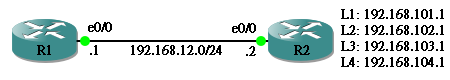
用 Next Hop IP
先用把 Static Route 設定好 Next Hop IP。
R1#show run | i route
ip route 192.168.101.0 255.255.255.0 192.168.12.2
ip route 192.168.102.0 255.255.255.0 192.168.12.2
ip route 192.168.103.0 255.255.255.0 192.168.12.2
ip route 192.168.104.0 255.255.255.0 192.168.12.2
R1#show ip route
Codes: C - connected, S - static, R - RIP, M - mobile, B - BGP
       D - EIGRP, EX - EIGRP external, O - OSPF, IA - OSPF inter area
       N1 - OSPF NSSA external type 1, N2 - OSPF NSSA external type 2
       E1 - OSPF external type 1, E2 - OSPF external type 2
       i - IS-IS, su - IS-IS summary, L1 - IS-IS level-1, L2 - IS-IS level-2
       ia - IS-IS inter area, * - candidate default, U - per-user static route
       o - ODR, P - periodic downloaded static route

Gateway of last resort is not set

C    192.168.12.0/24 is directly connected, Ethernet0/0
S    192.168.101.0/24 [1/0] via 192.168.12.2
S    192.168.102.0/24 [1/0] via 192.168.12.2
S    192.168.103.0/24 [1/0] via 192.168.12.2
S    192.168.104.0/24 [1/0] via 192.168.12.2
用 Next Hop IP 的話會發生什麽事?假設 R1 要送 Packet 到 192.168.101.1,跟據 Route Table,它會送到 Next Hop 192.168.12.2。但它不知道 192.168.12.2 在那裡啊?所以它要做一次 Recursive Lookup,然後找到 192.168.12.0/24 的 Next Hop Interface 是 E0/0。然後在 E0/0 發一個 ARP Request 問 192.168.12.2 的 MAC Address,於是 R2 回應並發 ARP Reply 使 R1 得知 MAC Address 並記錄在 ARP Table 之中。以後不管 Destination 是 192.168.101.1、192.168.102.1、192.168.103.1、 或 192.168.104.1,都不需要再發 ARP 了,因為 Next-hop 192.168.12.2 已經在 ARP Table 中。
R1#ping 192.168.101.1

Type escape sequence to abort.
Sending 5, 100-byte ICMP Echos to 192.168.101.1, timeout is 2 seconds:
.!!!!
Success rate is 80 percent (4/5), round-trip min/avg/max = 8/35/117 ms
R1#show arp
Protocol  Address          Age (min)  Hardware Addr   Type   Interface
Internet  192.168.12.1            -   cc01.064c.0000  ARPA   Ethernet0/0
Internet  192.168.12.2          101   cc02.065b.0000  ARPA   Ethernet0/0
用 Next Hop Interface
用 Interface 來當 Next Hop 的話,情況則有點不同。假設 R1 要送 Packet 到 192.168.101.1,跟據 Route Table,發現 Next Hop 是 Interface E0/0,沒有 Next Hop IP,Router 唯有用 ARP Request 在 E0/0 問 192.168.101.1 的 MAC Address,雖然 R2 的 E0/0 並非 192.168.101.1,但 R2 的 E0/0 居然會回覆自己的 MAC Address,原因是 Interface 的 Proxy ARP 預設是 Enable 的,如果 R2 的 Route Table 有 192.168.101.1 的話,Proxy ARP 設定會使 R2 的 E0/0 回覆。
R1#show run | i route
ip route 192.168.101.0 255.255.255.0 Ethernet0/0
ip route 192.168.102.0 255.255.255.0 Ethernet0/0
ip route 192.168.103.0 255.255.255.0 Ethernet0/0
ip route 192.168.104.0 255.255.255.0 Ethernet0/0
R1#show ip route
Codes: C - connected, S - static, R - RIP, M - mobile, B - BGP
       D - EIGRP, EX - EIGRP external, O - OSPF, IA - OSPF inter area
       N1 - OSPF NSSA external type 1, N2 - OSPF NSSA external type 2
       E1 - OSPF external type 1, E2 - OSPF external type 2
       i - IS-IS, su - IS-IS summary, L1 - IS-IS level-1, L2 - IS-IS level-2
       ia - IS-IS inter area, * - candidate default, U - per-user static route
       o - ODR, P - periodic downloaded static route

Gateway of last resort is not set

C    192.168.12.0/24 is directly connected, Ethernet0/0
S    192.168.101.0/24 is directly connected, Ethernet0/0
S    192.168.102.0/24 is directly connected, Ethernet0/0
S    192.168.103.0/24 is directly connected, Ethernet0/0
S    192.168.104.0/24 is directly connected, Ethernet0/0

R1#ping 192.168.101.1

Type escape sequence to abort.
Sending 5, 100-byte ICMP Echos to 192.168.101.1, timeout is 2 seconds:
.!!!!
Success rate is 80 percent (4/5), round-trip min/avg/max = 8/36/116 ms
R1#show arp
Protocol  Address          Age (min)  Hardware Addr   Type   Interface
Internet  192.168.101.1           0   cc02.065b.0000  ARPA   Ethernet0/0
Internet  192.168.12.1            -   cc01.064c.0000  ARPA   Ethernet0/0
Internet  192.168.12.2          112   cc02.065b.0000  ARPA   Ethernet0/0
問題來了,按照這個機制,即是說 R1 要為每個 Destination IP 查詢 ARP,這樣 ARP Record 就會迅速增加了!這會大大影響 Router 的效能,因此請避免使用這種 Static Route 設定。
R1#show arp
Protocol  Address          Age (min)  Hardware Addr   Type   Interface
Internet  192.168.104.1           0   cc02.065b.0000  ARPA   Ethernet0/0
Internet  192.168.101.1          12   cc02.065b.0000  ARPA   Ethernet0/0
Internet  192.168.103.1           0   cc02.065b.0000  ARPA   Ethernet0/0
Internet  192.168.102.1           0   cc02.065b.0000  ARPA   Ethernet0/0
Internet  192.168.12.1            -   cc01.064c.0000  ARPA   Ethernet0/0
Internet  192.168.12.2          124   cc02.065b.0000  ARPA   Ethernet0/0
用 Next Hop Interface 及 IP
如果必需要使用 Next Hop Interface 來限制 Packet 送到某個 Outgoing Interface 的話,最好把 Next Hop IP 也一併寫進去,目的是避免 ARP Record 記錄多個 Destination IP。
R1#show run | i route
ip route 192.168.101.0 255.255.255.0 Ethernet0/0 192.168.12.2
ip route 192.168.102.0 255.255.255.0 Ethernet0/0 192.168.12.2
ip route 192.168.103.0 255.255.255.0 Ethernet0/0 192.168.12.2
ip route 192.168.104.0 255.255.255.0 Ethernet0/0 192.168.12.2
透過這個設定,Packet 必然會使用 E0/0 作為 Outgoing Interface 而 Next Hop IP 則使用 192.168.12.2。問題是如果 E0/0 Down 了的話,所有以此 Interface 作為出口的 Route 就會消失。
R1#show arp
Protocol  Address          Age (min)  Hardware Addr   Type   Interface
Internet  192.168.12.1            -   cc01.064c.0000  ARPA   Ethernet0/0
Internet  192.168.12.2            3   cc02.065b.0000  ARPA   Ethernet0/0
Cisco Express Forwarding (CEF) 思科快遞交換
所以還有什麼問題呢?不夠快!試想想如果每次有 Packet 進來,都要從 Router Table 找 Route,而且可能不只一次 (因為 Recursive Lookup),但若果 Route Table 沒有更新的話,基本上每次結果都一様。為了省掉這個 Route Lookup 的程序,就出現了 CEF。CEF 可以把 Route Lookup 的結果保存在 CEF Table,當 Router 再次收到同一個 Destination 的 Packet 的話,不用找 Route Table 了,按 CEF Table 的紀錄直接轉走 (Switching)。所以 CEF 所做的是所謂 Route Once Switch Many。當 Route Table 有更新時,CEF Table 也會被更新。用 show ip cef 可以查看 CEF Table。
R1#show ip cef
Prefix              Next Hop             Interface
0.0.0.0/0           drop                 Null0 (default route handler entry)
0.0.0.0/32          receive
192.168.2.0/23      192.168.12.2         Ethernet0/0
192.168.12.0/24     attached             Ethernet0/0
192.168.12.0/32     receive
192.168.12.1/32     receive
192.168.12.2/32     192.168.12.2         Ethernet0/0
192.168.12.255/32   receive
192.168.101.0/24    192.168.12.2         Ethernet0/0
192.168.102.0/24    192.168.12.2         Ethernet0/0
192.168.103.0/24    192.168.12.2         Ethernet0/0
192.168.104.0/24    192.168.12.2         Ethernet0/0
224.0.0.0/4         drop
224.0.0.0/24        receive
255.255.255.255/32  receive
Policy Based Routing (PBR) 基於策略的路由
關於 Routing Decision 最後要說的是 Policy Based Routing。PBR 是一雙可以干預 Routing Decision 的幕後黑手,它可以把符合特定條件的 Packet,硬性設定其 Next Hop 而不查詢 Route Table 或 CEF Table。一個比較常用的例子為檢查 Packet 的 Source Address,為特定來源的 Packet 預設 Routing Path。現在用以下網絡來測試一下。
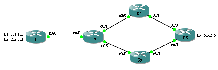
網絡只設定了基本的 EIGRP 作為 Dynamic Routing Protocol。各 Router 設定如下:
hostname R1
!
interface Loopback1
 ip address 1.1.1.1 255.255.255.255
!
interface Loopback2
 ip address 2.2.2.2 255.255.255.255
!
interface Ethernet0/0
 ip address 192.168.12.1 255.255.255.0
!
router eigrp 1
 network 0.0.0.0
 no auto-summary
hostname R2
!
interface Ethernet0/0
 ip address 192.168.12.2 255.255.255.0
!
interface Ethernet0/1
 ip address 192.168.23.2 255.255.255.0
!
interface Ethernet0/2
 bandwidth 5  // 故意減少 Bandwidth 來增加 Cost
 ip address 192.168.24.2 255.255.255.0
!
router eigrp 1
 network 0.0.0.0
 no auto-summary
hostname R3
!
interface Ethernet0/0
 ip address 192.168.23.3 255.255.255.0
!
interface Ethernet0/1
 ip address 192.168.35.3 255.255.255.0
!
router eigrp 1
 network 0.0.0.0
 no auto-summary
hostname R4
!
interface Ethernet0/0
 ip address 192.168.24.4 255.255.255.0
!
interface Ethernet0/1
 ip address 192.168.45.4 255.255.255.0
!
router eigrp 1
 network 0.0.0.0
 no auto-summary
hostname R5
interface Loopback1
 ip address 5.5.5.5 255.255.255.255
!
interface Ethernet0/0
 ip address 192.168.35.5 255.255.255.0
!
interface Ethernet0/1
 ip address 192.168.45.5 255.255.255.0
!
router eigrp 1
 network 0.0.0.0
 no auto-summary
由於故意減少了 R2 E0/2 的 Bandwidth 來增加 Cost,基於 EIGRP 的特性,R2 必然把所有要到 5.5.5.5 的 Packet 傳到 R3。請看 R2 的 Route Table。
R2#show ip route
Codes: C - connected, S - static, R - RIP, M - mobile, B - BGP
       D - EIGRP, EX - EIGRP external, O - OSPF, IA - OSPF inter area
       N1 - OSPF NSSA external type 1, N2 - OSPF NSSA external type 2
       E1 - OSPF external type 1, E2 - OSPF external type 2
       i - IS-IS, su - IS-IS summary, L1 - IS-IS level-1, L2 - IS-IS level-2
       ia - IS-IS inter area, * - candidate default, U - per-user static route
       o - ODR, P - periodic downloaded static route

Gateway of last resort is not set

C    192.168.12.0/24 is directly connected, Ethernet0/0
     1.0.0.0/32 is subnetted, 1 subnets
D       1.1.1.1 [90/409600] via 192.168.12.1, 00:30:03, Ethernet0/0
     2.0.0.0/32 is subnetted, 1 subnets
D       2.2.2.2 [90/409600] via 192.168.12.1, 00:30:03, Ethernet0/0
D    192.168.45.0/24 [90/332800] via 192.168.23.3, 00:28:07, Ethernet0/1
C    192.168.24.0/24 is directly connected, Ethernet0/2
     5.0.0.0/32 is subnetted, 1 subnets
D       5.5.5.5 [90/435200] via 192.168.23.3, 00:28:07, Ethernet0/1
C    192.168.23.0/24 is directly connected, Ethernet0/1
D    192.168.35.0/24 [90/307200] via 192.168.23.3, 00:28:15, Ethernet0/1
因此,在 R1 無論 Source IP 是什麽,都會用 R1 ➡️ R2 ➡️ R3 ➡️ R5 這條 Path。
R1#traceroute 5.5.5.5

Type escape sequence to abort.
Tracing the route to 5.5.5.5

  1 192.168.12.2 760 msec 456 msec 576 msec
  2 192.168.23.3 1664 msec 1260 msec 504 msec
  3 192.168.35.5 40 msec 32 msec 28 msec
R1#
R1#traceroute 5.5.5.5 source 1.1.1.1

Type escape sequence to abort.
Tracing the route to 5.5.5.5

  1 192.168.12.2 36 msec 20 msec 20 msec
  2 192.168.23.3 40 msec 44 msec 36 msec
  3 192.168.35.5 64 msec 60 msec 60 msec
R1#
R1#traceroute 5.5.5.5 source 2.2.2.2

Type escape sequence to abort.
Tracing the route to 5.5.5.5

  1 192.168.12.2 28 msec 8 msec 12 msec
  2 192.168.23.3 28 msec 24 msec 20 msec
  3 192.168.35.5 40 msec 32 msec 28 msec
重頭戲來了,現在我們在 R2 用 Route Map 去設定 PBR。
Step 1:設定 Access List
假設我們想干預來自 Source IP 2.2.2.2 而 Destination IP 5.5.5.5 的 Traffic,我們先設定 Access List。
R2(config)#access-list 100 permit ip host 2.2.2.2 host 5.5.5.5
Step 2:設定 Route Map
整個 Route Map 設定的意思是:如果 match access-list 100,就把 next-hop 改為 192.168.24.4。
R2(config)#route-map PBR permit 10
R2(config-route-map)# match ip address 100
R2(config-route-map)# set ip next-hop 192.168.24.4
Step 3:把 Route Map 放進 Interface
R2(config)#int ethernet 0/0
R2(config-if)# ip policy route-map PBR
於是,現在由 2.2.2.2 到 5.5.5.5 的 Traffic 就會被硬性更改 Next Hop 為 192.168.24.4,使用 R1 ➡️ R2 ➡️ R4 ➡️ R5 這條 path,其他 Source 則維持不變。
R1#traceroute 5.5.5.5

Type escape sequence to abort.
Tracing the route to 5.5.5.5

  1 192.168.12.2 1056 msec 1268 msec 280 msec
  2 192.168.23.3 40 msec 28 msec 16 msec
  3 192.168.35.5 52 msec 40 msec 40 msec
R1#
R1#traceroute 5.5.5.5 source 1.1.1.1

Type escape sequence to abort.
Tracing the route to 5.5.5.5

  1 192.168.12.2 52 msec 12 msec 8 msec
  2 192.168.23.3 20 msec 16 msec 20 msec
  3 192.168.35.5 32 msec 32 msec 28 msec
R1#
R1#traceroute 5.5.5.5 source 2.2.2.2

Type escape sequence to abort.
Tracing the route to 5.5.5.5

  1 192.168.12.2 40 msec 20 msec 20 msec
  2 192.168.24.4 40 msec 40 msec 40 msec
  3 192.168.45.5 32 msec 40 msec 28 msec
使用 PBR 時請了解,由於用 PBR 改動 Next Hop 後就不能應用 CEF 帶來的 Fast Switching,取而代之的是耗用了 CPU 資源去處理 Packet,在 Traffic 量大的 Interface 使用時必需留意 CPU 使用量。
相關主題
Jan Ho 2017-03-27
Posted In: Layer 3 網絡技術, menu-tall-2-zh-hant
發佈留言