目錄
前言
Spanning Tree Protocol (STP) 是一款 Layer 2 的 Protocol,一般在 Switch 上執行,主要目的是防止 Switch 在接駁時產生 Switching Loop。STP 是在學習網絡知識中一個重要的課題,必需深入了解其運作原理和操作流程。
Broadcast Storm
為什麼需要 STP 呢?請看看以下例子:
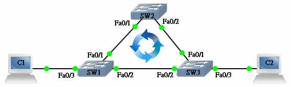
假設 C1 要傳送資料給 C2,但 C1 的 ARP Table 裡沒有 C2 的 MAC Address,因此 C1 送出一個 Broadcast ARP Request 想找 C2 的 MAC Address。這個 Broadcast 送到 SW1,由於 SW1 在 Fa0/3 收到 Broadcast,所以它會把 Broadcast 經由 Fa0/1 和 Fa0/2 送出去。同樣地,SW2 在 Fa0/1 收到後會在 Fa0/2 送出去,而 SW3 在 Fa0/2 收到後,就在 Fa0/1 和 Fa0/3 送出去,於是 SW2 和 SW1 又收到來自 SW3 的 Broadcast,然後它們也照樣在另一個出口送出,於是 Broadcast 不會停止地重覆輸送,這就稱為 Broadcast Storm,會造成 Switching Loop 的問題。
解決 Broadcast Storm 的方法是把網絡中其中一條連線斷開,阻止 Broadcast 在網絡上遊花園。問題是究竟斷開那一條連線好呢?各個 Switch 應該要有一致的共識,所以就有了 STP 這個機制,讓所有 Switch 溝通一下那些 port 要傳送資料,那些 port 應該休息不要傳送資料。
PVST+
PVST+ (Per VLAN Spanning Tree Plus) 是 Cisco Switch 預設的 STP 設定,透過 PVST+,Switch 可以建立一個 Loop-free (沒有 Loop) 的 topology。各 Switch 會按程序完成以下步驟:
- 在整個網絡裡選舉一隻 Root Switch
- 除了 Root Switch 外的其他各 Switch 都選擇一個 Root Port
- 所有網段選擇一個 Designated Port
- 把沒成為 Root Port 或 Designated Port 的 Port 成為 Non-Desiganted Port,這些 Port 會被 Blocking 去防止 Loop
Step 1: 選舉 Root Switch
PVST+ 會選 Switch Priority (或稱 Bridge Priority) 最小的 Switch 來成為 Root Switch,所以第一步要學習的是如何找出和計算 Switch 的 Priority。PVST+ 計算 Switch Priority 的公式是 Priority 值 + VLAN Number,Priority 值是可以設定的,預設值是 32768。每一個 VLAN 裡面的 Priority 可以各不相同,這就是所謂 Per VLAN STP 的精神,每一個 VLAN 都擁有屬於自己的 STP Topology。請看以下例子。
在 SW1 輸入 show spanning-tree 指令,請暫時跳過 Root ID 部份,先看 Bridge ID。Bridge ID 是本機的 Bridge 資料,可見本機的 Switch Priority 是 32769 (預設值 32768 + VLAN 1)。
SW1#show spanning-tree

 VLAN0001
   Spanning tree enabled protocol ieee
   Root ID    Priority    32769
              Address     0012.43bb.4340
              Cost        19
              Port        1 (FastEthernet0/1)
              Hello Time   2 sec  Max Age 20 sec  Forward Delay 15 sec

   Bridge ID  Priority    32769  (priority 32768 sys-id-ext 1)
              Address     0014.f21e.4980
              Hello Time   2 sec  Max Age 20 sec  Forward Delay 15 sec
              Aging Time 300

 <--Output Omitted-->
如果這隻 Switch 有 VLAN20 又會怎樣呢?建立 VLAN20 來試試看,VLAN20 的 Switch Priority = 32768 + 20 = 32788。所以,同一隻 Switch 裡面,不同 VLAN 的 Priority 是不相同的。
SW1(config)#vlan 20
 SW1(config-vlan)#end
 SW1#show spanning-tree

 VLAN0001
   Spanning tree enabled protocol ieee
   Root ID    Priority    32769
              Address     0012.43bb.4340
              Cost        19
              Port        1 (FastEthernet0/1)
              Hello Time   2 sec  Max Age 20 sec  Forward Delay 15 sec

   Bridge ID  Priority    32769  (priority 32768 sys-id-ext 1)
              Address     0014.f21e.4980
              Hello Time   2 sec  Max Age 20 sec  Forward Delay 15 sec
              Aging Time 300

 <--Output Omitted-->


 VLAN0020
   Spanning tree enabled protocol ieee
   Root ID    Priority    32788
              Address     0014.f21e.4980
              This bridge is the root
              Hello Time   2 sec  Max Age 20 sec  Forward Delay

 Bridge ID    Priority    32788  (priority 32768 sys-id-ext 20)
              Address     0014.f21e.4980
              Hello Time   2 sec  Max Age 20 sec  Forward Delay 15 sec
              Aging Time 300

<--Output Omitted-->
知道怎樣找 Switch Priority 了,如果想改 Priority 要怎樣做?一個簡單指令便 OK!用 spanning-tree vlan <vlan no> priority <priority>,留意 priority 必需是 4096 的倍數,現在試把 VLAN1 的 priority 改為 36864,把 VLAN 20 的 Priority 改為 8192。
SW1(config)#spanning-tree vlan 1 priority ?
   <0-61440>  bridge priority in increments of 4096

 SW1(config)#spanning-tree vlan 1 priority 36864
 SW1(config)#spanning-tree vlan 20 priority 8192
 SW1(config)#end
 SW1#show spanning-tree

 VLAN0001
   Spanning tree enabled protocol ieee
   Root ID    Priority    32769
              Address     0012.43bb.4340
              Cost        19
              Port        1 (FastEthernet0/1)
              Hello Time   2 sec  Max Age 20 sec  Forward Delay 15 sec

   Bridge ID  Priority    36865  (priority 36864 sys-id-ext 1)
              Address     0014.f21e.4980
              Hello Time   2 sec  Max Age 20 sec  Forward Delay 15 sec
              Aging Time 300

 <--Output Omitted-->


 VLAN0020
   Spanning tree enabled protocol ieee
   Root ID    Priority    8212
              Address     0014.f21e.4980
              This bridge is the root
              Hello Time   2 sec  Max Age 20 sec  Forward Delay 15 sec

   Bridge ID  Priority    8212   (priority 8192 sys-id-ext 20)
              Address     0014.f21e.4980
              Hello Time   2 sec  Max Age 20 sec  Forward Delay 15 sec
              Aging Time 300

 <--Output Omitted-->
看懂了 Switch Priority,現在正式開始談談 Root Switch 選舉,原來 Switch Priority 最小的 Switch 會成為 Root Switch,如果 Priority 相同就選 MAC Address 最小的。現在到這 3 隻 Switch 中看看 VLAN1 的 Priority 的情況。SW2 和 SW 3 的 Priority 都比較小,而 SW2 的 MAC Address 比 SW3 小,所以 SW2 成為 Root Switch。而且,在 SW2 見到一句很有霸氣的訊息:This bridge is the root,明確表示 SW2 就是 Root Switch!
SW1#show spanning-tree vlan 1

 VLAN0001
   Spanning tree enabled protocol ieee
   Root ID    Priority    32769
              Address     0012.43bb.4340
              Cost        19
              Port        1 (FastEthernet0/1)
              Hello Time   2 sec  Max Age 20 sec  Forward Delay 15 sec

   Bridge ID  Priority    36865  (priority 36864 sys-id-ext 1)
              Address     0014.f21e.4980
              Hello Time   2 sec  Max Age 20 sec  Forward Delay 15 sec
              Aging Time 300

 <--Output Omitted-->
SW2#show spanning-tree vlan 1

 VLAN0001
   Spanning tree enabled protocol ieee
   Root ID    Priority    32769
              Address     0012.43bb.4340
              This bridge is the root
              Hello Time   2 sec  Max Age 20 sec  Forward Delay 15 sec

   Bridge ID  Priority    32769  (priority 32768 sys-id-ext 1)
              Address     0012.43bb.4340
              Hello Time   2 sec  Max Age 20 sec  Forward Delay 15 sec
              Aging Time 300

 <--Output Omitted-->
SW3#show spanning-tree vlan 1

 VLAN0001
   Spanning tree enabled protocol ieee
   Root ID    Priority    32769
              Address     0012.43bb.4340
              Cost        19
              Port        2 (FastEthernet0/2)
              Hello Time   2 sec  Max Age 20 sec  Forward Delay 15 sec

   Bridge ID  Priority    32769  (priority 32768 sys-id-ext 1)
              Address     0014.6999.0100
              Hello Time   2 sec  Max Age 20 sec  Forward Delay 15 sec
              Aging Time 300

<--Output Omitted-->
如果我們想 SW1 成為 Root Switch 呢?有兩個方法,第一個方法是用 spanning-tree vlan <vlan no> priority <priority> 指令把 SW1 的 Priority 更改成更小的值。第二個方法是用 spanning-tree vlan 1 root primary 直接把 SW1 設定成 Root,其實這個指令也只是幫你把 Priority 調細而已。
SW1(config)#spanning-tree vlan 1 root primary
 SW1(config)#end
 SW1#show spanning-tree vlan 1

 VLAN0001
   Spanning tree enabled protocol ieee
   Root ID    Priority    24577
              Address     0014.f21e.4980
              This bridge is the root
              Hello Time   2 sec  Max Age 20 sec  Forward Delay 15 sec

   Bridge ID  Priority    24577  (priority 24576 sys-id-ext 1)
              Address     0014.f21e.4980
              Hello Time   2 sec  Max Age 20 sec  Forward Delay 15 sec
              Aging Time 15

 <--Output Omitted-->
所以,現在我們在 VLAN1 選擇了 SW1 為 Root Switch。
Step 2: 選擇 Root Port
然後,除了 Root Switch 外,每隻 Switch 都會選擇一個 Root Port,Root Port 是最「接近」Root Switch 的 Port,怎樣計算最接近呢?Switch 會按 Interface 的 Bandwidth 來計算 Cost,不應該說計算,其實是死背的,請看下表:
| Bandwidth (Mbps) | 4 | 10 | 16 | 45 | 100 | 155 | 1000 | 10000 |
|---|---|---|---|---|---|---|---|---|
| Cost | 250 | 100 | 62 | 39 | 19 | 14 | 4 | 2 |
SW1
由於 SW1 自己本身是 Root Switch,因此不用選擇 Root Port。
SW2
SW2 用 Fa0/1 要經過 1 條 100Mb Link (Cost: 19),而用 Fa0/2 要經過 2 條 100Mb Link (Cost = 19+19=38),因此 SW2 選用 Fa0/1 為 Root Port。
SW3
同樣道理,SW3 用 Fa0/1 要經過 1 條 100Mb Link (Cost: 19),而用 Fa0/2 要經過 2 條 100Mb Link (Cost = 19+19=38),因此 SW3 選用 Fa0/1 為 Root Port。用 show spanning-tree 可以看到那個 Port 被定性為 Root Port。
SW2#show spanning-tree | begin Interface
 Interface        Role Sts Cost      Prio.Nbr Type
 ---------------- ---- --- --------- -------- --------------------------------
 Fa0/1            Root FWD 19        128.1    P2p
 Fa0/2            Desg FWD 19        128.2    P2p
SW3#show spanning-tree  | begin Interface
 Interface        Role Sts Cost      Prio.Nbr Type
 ---------------- ---- --- --------- -------- --------------------------------
 Fa0/1            Root FWD 19        128.1    P2p
 Fa0/2            Altn BLK 19        128.2    P2p
如果想強迫 SW2 的 Fa0/2 成為 Root Port 可以嗎?我們可以用 Interface 指令 spanning-tree vlan <vlan no> cost <cost> 來增加 Fa0/1 的 Cost:
SW2(config)#int fastEthernet 0/1
 SW2(config-if)#spanning-tree vlan 1 cost 40
 SW2(config-if)#end
 SW2#show spanning-tree | begin Interface
 Interface        Role Sts Cost      Prio.Nbr Type
 ---------------- ---- --- --------- -------- --------------------------------
 Fa0/1            Altn BLK 40        128.1    P2p
 Fa0/2            Root FWD 19        128.2    P2p
現在我們把更改 Cost 的指令移除,於是 Root Port 位置就如下圖。
Step 3: 選擇 Designated Port 與 Non-Designated Port
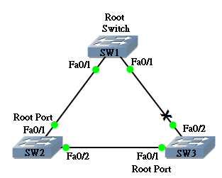
每一段網段只容許一個 Port 成為 Designated Port,網段裡面最接近 Root Switch (Cost 最少) 的 Port 成為 Designated Port。如果網段裡只有兩個 Port,在別無選擇下,與 Root Port 相對的 Port 必然成為 Designated Port,因此 SW1 的 Fa0/1 與 Fa0/2 成為 Designated Port。問題在於 SW2 與 SW3 的連線,那一個 Port 成為 Designated Port 呢?在 Designated Port 的選擇與選擇 Root Switch 相似,同樣用 Switch Priority 較小者成為 Designated Port,如果 Switch Priority 相同,則 MAC Address 較小者勝出。SW2 的 Priority 為 32769,SW3 的 Priority 也是 32769,不過 SW2 的 MAC Address 較小,因此 SW2 的 Fa0/2 成為 Designated Port,會傳送訊息 (Forwarding) 而 SW3 的 Fa0/2 則會成為 Non-Designated Port,不傳送也不接收訊息 (Blocking),這樣就導絕了 Loop。Non-Designated Port 會被顥示為 Altn (Alternate Port) 或 Back (Backup Port),在傳統的 STP 中並沒分別,總之 State 都是 Blocking 就是了。
SW2#show spanning-tree

 VLAN0001
   Spanning tree enabled protocol ieee
   Root ID    Priority    24577
              Address     0014.f21e.4980
              Cost        19
              Port        1 (FastEthernet0/1)
              Hello Time   2 sec  Max Age 20 sec  Forward Delay 15 sec

   Bridge ID  Priority    32769  (priority 32768 sys-id-ext 1)
              Address     0012.43bb.4340
              Hello Time   2 sec  Max Age 20 sec  Forward Delay 15 sec
              Aging Time 300

 Interface        Role Sts Cost      Prio.Nbr Type
 ---------------- ---- --- --------- -------- --------------------------------
 Fa0/1            Root FWD 19        128.1    P2p
 Fa0/2            Desg FWD 19        128.2    P2p
SW3#show spanning-tree

 VLAN0001
   Spanning tree enabled protocol ieee
   Root ID    Priority    24577
              Address     0014.f21e.4980
              Cost        19
              Port        1 (FastEthernet0/1)
              Hello Time   2 sec  Max Age 20 sec  Forward Delay 15 sec

   Bridge ID  Priority    32769  (priority 32768 sys-id-ext 1)
              Address     0014.6999.0100
              Hello Time   2 sec  Max Age 20 sec  Forward Delay 15 sec
              Aging Time 300

 Interface        Role Sts Cost      Prio.Nbr Type
 ---------------- ---- --- --------- -------- --------------------------------
 Fa0/1            Root FWD 19        128.1    P2p
 Fa0/2            Altn BLK 19        128.2    P2p
STP 的選舉準則
透過上面的例子,我們知道要完成整個 STP 流程,中間經過幾個選舉,分別是選 Root Switch、選 Root Port 和選 Designated Port。這幾個選舉的決擇其實都源自是同一套準則如下:
準則 1:比 Bridge ID,小的勝出 (只有選 Root Switch 時使用)
所謂 Bridge ID 就是一串 16 Bits 的 Priority 和 48 Bits MAC Address 組成的值,由於 Priority 在前,MAC Address 在後,基本上 Priority 已可定勝負,除非 Priority 相同,則要看 MAC Address。在一隻 Switch 之中,Priority 可人工調校,而 MAC Address 則不可改變。
準則 2:比 Root Cost ,小的勝出
在選擇 Root Port 和 Designated Port 時,就要比 Root Cost。Root Cost 就是要到達 Root Switch 所需要的 Cost 總和,可以人工調校。
準則 3:比對方的 Bridge ID,小的勝出
如 Root Cost 相同的話,就要比對方的 Bridge ID。
準則 4:比對方的 Port ID,小的勝出
最後,會用 Port ID 來比較。Port ID 是一串 4 Bits 的 Priority 和 12 Bits Interface Number 所組成的值。由於 Priority 在前,一般用 Priority 已可定勝負,如果 Priority 相同,則要看 Interface Number,由於一隻 Switch 上的 Interface Number 必然不同,所以準則 4 必可分出勝負。
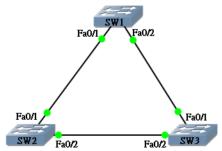
現在我們用一個簡單的網絡,重新審視一下這 4 個準則。

Step 1: 選舉 Root Switch
準則 1:比 Bridge ID,小的勝出
準則 2:比 Root Cost,小的勝出
準則 3:比對方的 Bridge ID,小的勝出
準則 4:比對方的 Port ID,小的勝出
先看看兩隻 Switch 的 Priority 與 MAC Address:
SW1#show spanning-tree

 VLAN0001
   Spanning tree enabled protocol ieee
   Root ID    Priority    32769
              Address     0012.43bb.4340
              Cost        19
              Port        1 (FastEthernet0/1)
              Hello Time   2 sec  Max Age 20 sec  Forward Delay 15 sec

   Bridge ID  Priority    32769  (priority 32768 sys-id-ext 1)
              Address     0014.f21e.4980
              Hello Time   2 sec  Max Age 20 sec  Forward Delay 15 sec
              Aging Time 15
SW2#show spanning-tree

 VLAN0001
   Spanning tree enabled protocol ieee
   Root ID    Priority    32769
              Address     0012.43bb.4340
              This bridge is the root
              Hello Time   2 sec  Max Age 20 sec  Forward Delay 15 sec

   Bridge ID  Priority    32769  (priority 32768 sys-id-ext 1)
              Address     0012.43bb.4340
              Hello Time   2 sec  Max Age 20 sec  Forward Delay 15 sec
              Aging Time 15
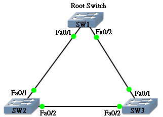
由於 Bridge ID 的 Priority 部份相同,因此比較 MAC Address,SW2 MAC Address 較小,因而勝出成為 Root Bridge。因為 MAC Address 不會相同,必能分勝負,因此 Root Switch 的選擇透過準則 1 必可成功選出,不必到準則 2-4。
Step 2: 選擇 Root Port
準則 1:比 Bridge ID,小的勝出 (不用準則 1)
準則 2:比 Root Cost,小的勝出
準則 3:比對方的 Bridge ID,小的勝出
準則 4:比對方的 Port ID,小的勝出
準則 1:比 Bridge ID,小的勝出
準則 2:比 Root Cost,小的勝出
準則 3:比對方的 Bridge ID,小的勝出
準則 4:比對方的 Port ID,小的勝出
在預設的情況之下,SW1 的 Fa0/1 與 Fa0/2 Bandwidth 相同,因此 Cost 相同,無法用準則 2 分勝負。(當然,我們可以選擇更改 Interface 的 Bandwdith,或使用 spanning-tree vlan <vlan no> cost <cost> 來調整 cost。)
準則 1:比 Bridge ID,小的勝出
準則 2:比 Root Cost,小的勝出
準則 3:比對方的 Bridge ID,小的勝出
準則 4:比對方的 Port ID,小的勝出
由於 SW1 的 Fa0/1 與 Fa0/2 都接上同一隻 Switch,因此「對方的 Bridge ID」必然相同,所以準則 3 仍無法分勝負。
準則 1:比 Bridge ID,小的勝出
準則 2:比 Root Cost,小的勝出
準則 3:比對方的 Bridge ID,小的勝出
準則 4:比對方的 Port ID,小的勝出
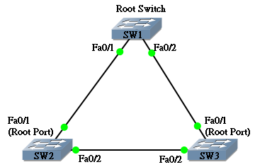
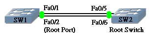
從 SW2 可以查看 Fa0/5 和 Fa0/6 的 Port ID 分別是 128.5 和 128.6,由於 128.5 比較小,與其連接著的 SW1 的 Fa0/1 便成為 Root Port 了。由於 Interface Number 不能更改,因此準則 4 必能分勝負。
SW2#show spanning-tree | begin Interface
 Interface        Role Sts Cost      Prio.Nbr Type
 ---------------- ---- --- --------- -------- --------------------------------
 Fa0/5            Desg FWD 19        128.5    P2p
 Fa0/6            Desg FWD 19        128.6    P2p
SW1#show spanning-tree | begin Interface
 Interface        Role Sts Cost      Prio.Nbr Type
 ---------------- ---- --- --------- -------- --------------------------------
 Fa0/1            Root FWD 19        128.1    P2p
 Fa0/2            Altn BLK 19        128.2    P2p
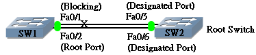
如果想改變 Port Priority,可用 spanning-tree port-priority <priority>,例如試試把 SW2 的 Fa0/6 的 Port Priority 改為 64。
SW2(config)#interface fastEthernet 0/6
 SW2(config-if)#spanning-tree port-priority 64
SW2#show spanning-tree | begin Interface
 Interface        Role Sts Cost      Prio.Nbr Type
 ---------------- ---- --- --------- -------- --------------------------------
 Fa0/5            Desg FWD 19        128.5    P2p
 Fa0/6            Desg FWD 19         64.6    P2p
於是 SW1 的 Fa0/2 成為 Root Port,因為準則 4,對方的 Port ID 比較小。
SW1#show spanning-tree | begin Interface
 Interface        Role Sts Cost      Prio.Nbr Type
 ---------------- ---- --- --------- -------- --------------------------------
 Fa0/1            Altn BLK 19        128.1    P2p
 Fa0/2            Root FWD 19        128.2    P2p
Step 3: 選擇 Designated Port 與 Blocked Port
與 Root Port 相對的 Port 必然成為 Designated Port,因此 SW2 的 Fa0/6 順理成章變成 Designated Port。問題在於 SW1 的 Fa0/1 與 SW2 的 Fa0/5 誰勝誰負?
準則 1:比 Bridge ID,小的勝出 (不用準則 1)
準則 2:比 Root Cost,小的勝出
準則 3:比對方的 Bridge ID,小的勝出
準則 4:比對方的 Port ID,小的勝出
準則 1:比 Bridge ID,小的勝出
準則 2:比 Root Cost,小的勝出
準則 3:比對方的 Bridge ID,小的勝出
準則 4:比對方的 Port ID,小的勝出
SW2 的 Root Cost 當然 比 SW1 小,所以 SW2 的 Fa0/5 勝出成為 Designated Port,而 SW1 的 Fa0/1 會成為 Non-Designated Port (Blocking)。(也有教學說 Root Switch 的 Port 必然是 Designated Port,記憶方法不同,道理相同。)
BPDU
Bridge Protocol Data Unit (BPDU) 是 Switch 間用來傳送 STP 資訊的 Frame,BPDU 裡的資訊包括:Bridge ID、Cost 和 Port ID 等。一個網絡中應該只有 Root Switch 發放 BPDU,不過當任何一隻 Switch 剛啟動時,它都會認為自己是 Root Switch 而發放 BPDU,直至它收到一個包含 Bridge ID 較小的 BPDU (稱為 Superior BPDU) 時,它才知道自己在 Root Switch 選舉中落敗了而停止發放 BPDU。
BPDU 預設每 2 秒發放一次,稱為 BPDU Hello Time,而 Switch 接收到的 BPDU 只會被儲存 20 秒 (Max-age),即是說如果 Switch 過了 20 秒也沒有收到 BPDU,也沒有在其他 Port 收到 BPDU 的話,就會判斷 Root Switch 已經死了,它又會再次認定自己是 Root Switch,再次發放 BPDU 了。STP 還有另一個 Timer 稱為 Forward Delay,是用作調校 Listening 和 Learning 狀態的時間,關於 Listening 和 Learning 狀態會在下一節說明。
如果想知道 Timer 的設定值,可以用 show spanning-tree vlan <vlan no> 指令。
SW1#show spanning-tree vlan 1

 VLAN0001
   Spanning tree enabled protocol ieee
   Root ID    Priority    24577
              Address     0014.f21e.4980
              This bridge is the root
              Hello Time   2 sec  Max Age 20 sec  Forward Delay 15 sec

   Bridge ID  Priority    24577  (priority 24576 sys-id-ext 1)
              Address     0014.f21e.4980
              Hello Time   2 sec  Max Age 20 sec  Forward Delay 15 sec
              Aging Time 300

<--Output Omitted-->
更改這些 Timer 的指令如下:
SW1(config)#spanning-tree vlan 1 hello-time 4
 SW1(config)#spanning-tree vlan 1 max-age 26
 SW1(config)#spanning-tree vlan 1 forward-time 20
SW1#show spanning-tree vlan 1

 VLAN0001
   Spanning tree enabled protocol ieee
   Root ID    Priority    24577
              Address     0014.f21e.4980
              This bridge is the root
              Hello Time   4 sec  Max Age 26 sec  Forward Delay 20 sec

   Bridge ID  Priority    24577  (priority 24576 sys-id-ext 1)
              Address     0014.f21e.4980
              Hello Time   4 sec  Max Age 26 sec  Forward Delay 20 sec
              Aging Time 300

<--Output Omitted-->
我們也可以叫 Switch 自動調整這 3 個 Timer,只要告訴 Root Switch 網絡的 Diameter 是多少,所謂 Diameter 就是網絡由一端去到另一端最遠跳過多少隻 Switch?即由一邊去到另一邊有多遠?Switch 會按這個距離去設定 Timer:
SW1(config)#spanning-tree vlan 1 root primary diameter ?
   <2-7>  Maximum number of bridges between any two end nodes

 SW1(config)#spanning-tree vlan 1 root primary diameter 5
 SW1(config)#end
 SW1#show spanning-tree vlan 1

 VLAN0001
   Spanning tree enabled protocol ieee
   Root ID    Priority    24577
              Address     0014.f21e.4980
              This bridge is the root
              Hello Time   2 sec  Max Age 16 sec  Forward Delay 12 sec

   Bridge ID  Priority    24577  (priority 24576 sys-id-ext 1)
              Address     0014.f21e.4980
              Hello Time   2 sec  Max Age 16 sec  Forward Delay 12 sec
              Aging Time 300

<--Output Omitted-->
由於更改 STP 的 Timer 有一定風險,如果設定值不理想會導致整個網絡癱瘓,因此不建議更改,就算要更改都請盡量使用 Diameter 指令,這樣可以使用 Cisco 的建議值,Diameter 與 Timer 的對照表如下:
| Diameter | 2 | 3 | 4 | 5 | 6 | 7 |
|---|---|---|---|---|---|---|
| Hello Time | 2 | 2 | 2 | 2 | 2 | 2 |
| Max Age | 10 | 12 | 14 | 16 | 18 | 20 |
| Forward Delay | 7 | 9 | 10 | 12 | 13 | 15 |
Port State
在 STP 中,一個 Port 由 Down 變成 Up,中間經歷了幾個狀態,了解這些狀態是學習 STP 重要的一環。
Disabled
Port 被 Shutdown 了,在這狀態下該 Port 不會傳送或接收任何 Frame。
Blocking
不會傳送或接收 Data Frame,但仍會接收 BPDU,目的是 Blocking Port 有需要知道現時 Spanning Tree 的狀態,當有需要時可以跳到 Listening。為了防止 Loop 發生,一隻 Switch 啟動時,所有 Port 都會先進入 Blocking。
Listening
當 Switch 知道某個 Port 需要啟動時,就會把 Port 由 Blocking 轉到 Listening,在這個狀態下,Port 會傳送及接收 BPDU,但仍不會傳送 Data Frame,它會參與 Root Switch 選舉、Root Port 選舉和 Designated Port 選舉。這個狀態會維持一個 Forward Delay 的時間 (預設 15 秒)。
Learning
如果一個 Port 在選舉時成功成為 Root Port 或 Designated Port,它便會進入 Learning,Port 會收發 BPDU,而且會開始留意傳過來的 Data Frame,把 MAC Address 記錄到 MAC Address Table,但仍然不會傳送 Data Frame,這樣做的目的是希望這個 port 在開始工作之前,先盡量記錄 MAC Address,免得稍後時間需要把 Frame Flood 到所有 Port 而製造不必要的 Traffic。這個狀態會維持一個 Forward Delay 的時間 (預設 15 秒)。
Forwarding
最後,Port 會變成 Forwarding,會收發 BPDU,記錄 MAC Address,也會傳送 Data Frame。
| 狀態 | Disabled | Blocking | Listening | Learning | Forwarding |
|---|---|---|---|---|---|
| 接收 BPDU | NO | YES | YES | YES | YES |
| 發送 BPDU | NO | NO | YES | YES | YES |
| Learn MAC Address | NO | NO | NO | YES | YES |
| Forward Data Frame | NO | NO | NO | NO | YES |
| 維持時間 | 直至 no shutdown | 直至 Topology 有轉變 | Forward Delay (預設 15 秒) | Forward Delay (預設 15 秒) | 直至 Shutdown 或不再成為 Root Port / Designated Port |
如想觀察 Port 狀態的變化,可以使用 debug spanning-tree events。
SW1#debug spanning-tree events
 Spanning Tree event debugging is on
 SW1#config terminal
 Enter configuration commands, one per line.  End with CNTL/Z.
 SW1(config)#int fastEthernet 0/1
 SW1(config-if)#shutdown
 SW1(config-if)#
 01:19:22: %LINK-5-CHANGED: Interface FastEthernet0/1, changed state to administr atively down
 01:19:22: STP: VLAN0001 Topology Change rcvd on Fa0/2
 01:19:23: %LINEPROTO-5-UPDOWN: Line protocol on Interface FastEthernet0/1, chang ed state to down
 SW1(config-if)#no shutdown
 SW1(config-if)#
 01:19:29: %LINK-3-UPDOWN: Interface FastEthernet0/1, changed state to up
 01:19:32: set portid: VLAN0001 Fa0/1: new port id 8001
 01:19:32: STP: VLAN0001 Fa0/1 -> listening
 01:19:33: %LINEPROTO-5-UPDOWN: Line protocol on Interface FastEthernet0/1, chang ed state to up
 01:19:47: STP: VLAN0001 Fa0/1 -> learning
 01:20:02: STP: VLAN0001 Fa0/1 -> forwarding
Topology Change
當 STP 選好了 Root Switch、Root Port 和 Designated Port 之後,就會進入收斂 (Convergence) 的狀態,在此時,只要網絡 Topology 沒有改變,STP 就會很穩定地維持原狀。不過世事無常,我們不時會在網絡添置新的 Switch,又或者開關某些 Switch 都會令到網絡 Topology 改變,當 Switch 發現網絡 Topology 改變,就會向 Root Switch 發一個 Topology Change Notification (TCN) BPDUs,究竟怎樣才算一個 Topology Change 呢?就是以下兩個情況其中之一:
- 當一個 Port 轉到 Forwarding 狀態
- 當一個 Listening 或 Forwarding 的 Port 轉到 Blocking 或 Disabled
當 root switch 收到 TCN 之後,會通知 STP 裡面所有其他 Switch 有 Topology Change,其他 Switch 收到通知後就會把 MAC Address Table 的 timeout 時間由 300 秒改為 15 秒 (Forward Delay),這樣做是因為基於 Topology 有改變,MAC Address Table 的紀錄已經不可靠,因而縮短其保存時間,保證 MAC Address Table 盡快被更新,這狀態會維持 35 秒 (Forward Delay + Max Age)。
PortFast
不過,這個 Topology Change 機制帶來了一個問題,試想想如果在 Switch 插入一部 PC,PC 是不會改變 STP 的 Topology,可是插入 PC 時令 Port 轉到 Forwarding 狀態,又或者重新啟動 PC 時,都會令 STP 以為有 Topology Change,而讓整個 Network Switch 縮減 ARP Table Timeout 時間,這是多餘的。另一方面,插入 PC 的這個 Port 亦要經歷 Blocking → Listening → Learning → Forwarding 的過程而等待 30 秒才能上線。為了解決這兩個問題,Cisco 的 Switch 可以開啟 PortFast,開啟 PortFast 可以讓 Port 在插入後跳過 Listening 和 Learning 而立刻轉成 Forwarding。如果一個設成 PortFast 的 Port 收到 BPDU 的話 (即插入了 Switch) 就會依正常情序進入 Listening 和 Learning。
要啟動 PortFast 有兩個方法,可以在 Interface 用 spanning-tree portfast 指令:
SW1(config)#interface fastEthernet 0/1
 SW1(config-if)#spanning-tree portfast
又或者在 Global 用 spanning-tree portfast default 指令把所有 port 預設成 PortFast。
SW1(config)#spanning-tree portfast default
UplinkFast
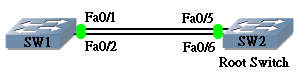
接下來,我們討論以下這個網絡:
圖中 SW2 是 Root Switch,SW1 的 Fa0/2 是 Forwarding 而 Fa0/1 處於 Blocking 狀態,當 Fa0/2 的 Link 因為某些原因而死掉,我們稱之為 Directly Fail,SW1 會立刻進行 STP 計算,不過 Fa0/1 由 Blocking 轉到 Forwarding 的狀態需要 30 秒時間,而 30 秒等待時間對於一個網絡來說可謂完全不能接受!而 Cisco 對此的解決方案為 UplinkFast。啟動了 UplinkFast 的 Switch 會選 1 個 Blocking Port 設為 Standby 狀態,當 Root Port 死掉時,Standby 的 Port 立刻轉成 Forwarding,省掉 30 秒等候時間。
開啟 UplinkFast 的指令為 spanning-tree uplinkfast。請注意,此指令不應在 Root Switch 執行。
SW1(config)#spanning-tree uplinkfast
輸入此指令後,會發現 Switch priority 會被改成 49152,而所有 Port 的 Cost 都會被加 3000。
輸入前:
SW1#show spanning-tree

 VLAN0001
   Spanning tree enabled protocol ieee
   Root ID    Priority    32769
              Address     0012.43bb.4340
              Cost        19
              Port        1 (FastEthernet0/1)
              Hello Time   2 sec  Max Age 20 sec  Forward Delay 15 sec

   Bridge ID  Priority    32769  (priority 32768 sys-id-ext 1)
              Address     0014.f21e.4980
              Hello Time   2 sec  Max Age 20 sec  Forward Delay 15 sec
              Aging Time 300

 Interface        Role Sts Cost      Prio.Nbr Type
 ---------------- ---- --- --------- -------- --------------------------------
 Fa0/1            Root FWD 19        128.1    P2p
 Fa0/2            Altn BLK 19        128.2    P2p
輸入後:
SW1#show spanning-tree

 VLAN0001
   Spanning tree enabled protocol ieee
   Root ID    Priority    32769
              Address     0012.43bb.4340
              Cost        3019
              Port        1 (FastEthernet0/1)
              Hello Time   2 sec  Max Age 20 sec  Forward Delay 15 sec

   Bridge ID  Priority    49153  (priority 49152 sys-id-ext 1)
              Address     0014.f21e.4980
              Hello Time   2 sec  Max Age 20 sec  Forward Delay 15 sec
              Aging Time 300
   Uplinkfast enabled

 Interface        Role Sts Cost      Prio.Nbr Type
 ---------------- ---- --- --------- -------- --------------------------------
 Fa0/1            Root FWD 3019      128.1    P2p
 Fa0/2            Altn BLK 3019      128.2    P2p
BackboneFast
Directly Fail 可用 UplinkFast 解決,現在討論一下 Indirectly Fail 會出現什麼狀況。
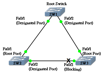
上圖中 SW1 是 Root Switch,SW2 的 Fa0/1 及 SW3 的 Fa0/1 是 Root Port,當 SW1 與 SW2 之間的連線中斷,雖然 SW2 會察覺得到,但 SW3 是懵然不知的,它仍然等待接收由 SW1 傳出經 SW2 傳來的 BPDU,直至 20 秒 (Max Age) 過去了都收不到 BPDU 的話,SW3 才會把 BPDU 棄掉,然後選擇把 Fa0/2 轉成 Root Port,不過由 Blocking 至 Forwarding 又用了 30 秒,所以 SW1 要等待總共 50 秒 (20 + 30) 才能再次與 SW3 連上。如果任由這情況發生,網管人員的電話早已響過不停!Cisco 對此問題的解決方案就是 BackboneFast。
BackboneFast 想解決的問題在於那等待的 20 秒,如果 Switch 開啟了 BackboneFast,當發現收不到 BPDU 時就會主動在 Root Port 發送一個 Root Link Query (RLQ),如果 Root Switch 收到的話就會回覆一個 RLQ reply,當發送 RLQ 的 Switch 收到 reply,即是說從 Root Port 仍然能夠聯絡上 Root Switch 喔,剛才收不到 BPDU 可能只是少許的不穩定,它會繼續相信這條 Path 能夠去到 Root Switch。但是,如果發了 RLQ 又收不到 Reply 的話,證明這個 Root Port 真的去不到 Root Switch 了,它就會立刻進行 STP 運算來找另一條能去 Root Port 的 Path,這就省掉呆呆的等待 20 秒時間。如果配合 UplinkFast 使用的話,甚至可以無間斷地跳轉 Root Port。
要使用 BackboneFast,必需在所有 Switch 使用 spanning-tree backbonefast 指令。
SW1(config)#spanning-tree backbonefast
保護 STP Topology
當 STP Topology 設計好之後,應該加以保護,尤其 Root Switch 的角色不可被新加的 Switch 搶去,因為 STP Topology 的改變會導致 Port Up/Down,產生斷線問題,而且會令 Frame 不是走最佳路徑而出現 delay,所以加入新的 Switch 時要小心行事,留意 Switch Priority 的設定。不過,網絡接頭分佈在各處,User 可能會插入一些未經授權的 Switch,網管人員又怎能看守著每一個 Port 呢?Cisco Switch 提供了幾個方案讓網管人員保護 STP。
Root Guard
Root Guard 可以保護 STP 免受 Switch Priority 小的 Switch 搶了 Root Switch 的位置。開啟方法如下:
SW1(config)#int fastEthernet 0/8
 SW1(config-if)#spanning-tree guard root
當有一隻 Switch Priority 比現時 Root Switch 小的 Switch 插入這個 Port,這個 Port 會處於 Root Inconsistent 的狀態,它會被 Blocking 而不會傳送或接收 Frame。
SW1#show spanning-tree inconsistentports

 Name                 Interface              Inconsistency
 -------------------- ---------------------- ------------------
 VLAN0001             FastEthernet0/8        Root Inconsistent

 Number of inconsistent ports (segments) in the system : 1

 SW1#show spanning-tree vlan 1 | begin Interface
 Interface        Role Sts Cost      Prio.Nbr Type
 ---------------- ---- --- --------- -------- --------------------------------
 Fa0/1            Desg FWD 19        128.1    P2p
 Fa0/8            Desg BKN*19        128.8    P2p *ROOT_Inc
 Gi0/1            Desg FWD 4         128.9    Edge P2p
BPDU Guard
如果嫌 Root Guard 也不夠穩當,可以用 BPDU Guard。BPDU Guard 比 Root Guard 更嚴緊,只要收到 BPDU Message,無論它是否要成為 Root Switch,都立刻把此 Port 變成 Error Disable 關上。開啟方法如下:
SW1(config)#int fastEthernet 0/7
 SW1(config-if)#spanning-tree bpduguard enable
當一隻 Switch 插入,這個 Port 就被 Error Disable。
SW1#show interfaces fastEthernet 0/7
 FastEthernet0/7 is down, line protocol is down (err-disabled)
   Hardware is Fast Ethernet, address is 0014.f21e.4987 (bia 0014.f21e.4987)
   MTU 1500 bytes, BW 100000 Kbit, DLY 100 usec,
      reliability 255/255, txload 1/255, rxload 1/255

<--Output Omitted-->
解禁的方法是:先把 Switch 拔掉,然後把 Port shutdown 再 no shutdown。
SW1(config)#int fastEthernet 0/7
 SW1(config-if)#shutdown
 SW1(config-if)#no shutdown
BPDU Filtering
就算開啟了 Root Guard 或者 BPDU Guard,Switch 仍然會在這個 Port 對外發送 BPDU Message,如果對方不是 Switch,發送 BPDU 是不必要的。BPDU Filtering 可以防止 Switch 對外發送 BPDU Message。BPDU Filtering 可以配合 PortFast 在 Global 啟動,或者在 Interface 中啟動。啟動了 BPDU Filtering 後這個 Port 就不會再發送 BPDU Message。至於在這個 Port 收到 BPDU 的話則按情況作出不同處理:
如果是配合 PortFast 在 Global 啟動的話,這個 Port 會依正常情序進行 STP,依次進入 Listening 、 Learning 和 Forwarding 狀態。配合 PortFast 啟動方法如下:
SW1(config)#spanning-tree portfast bpdufilter default
 SW1(config)#interface GigabitEthernet0/6
 SW1(config-if)#spanning-tree portfast
如果是在 Interface 啟動的話,這個 Port 會無視 BPDU Message。當這個 Port 變成 Forwarding 後就會有機會造成 Switch Loop,務必特別注意!
SW1(config)#int fastEthernet 0/6
 SW1(config-if)#spanning-tree bpdufilter enable
UDLD
一般網絡線是有來有往的,即有傳送 (transmit) 有接收 (receive),這叫做 bidirectional。但如果網絡線有固障,發生單向傳輸 (unidirectional) 的問題,可能會導致 Port 接收不到 BPDU。試想想一個 Blocking Port 不斷接收到 BPDU 而令自己維持在 Blocking 的狀態,一旦發生 unidirectional 問題,令 Blocking Port 收不到 BPDU,過了 Max Age 20 秒之後,Blocking Port 就會嘗試進入選舉流程而最後變成 Forwarding,這就會造成 Switch Loop 問題。這程況最有可能發生在光纖線,Cisco 使用 Unidirectional Link Detection (UDLD) 來針對這個問題保護 STP。
當網絡線的兩端 Port 開啟了 UDLD,Port 就會不斷向對方發出檢測,如果對方有回應,代表運作正常,但如果收不到對方回應,UDLD 就會因應兩個不同的模式作出處理。
Normal Mode
在 Normal Mode 中,Port 不會被 Disable,但標記成 Undetermined State。
在 Global 把所有 Port 啟動 UDLD Normal Mode:
SW1(config)#udld enable
或者在 Interface 為某個 Port 啟動 UDLD Normal Mode:
SW1(config-if)#udld port
用 show udld 指令查看,udld 預設每 7 秒傳送檢測訊息,如果 5 秒內收不到回覆則判為 unidirectional:
SW1#show udld

 Interface Fa0/1
 ---
 Port enable administrative configuration setting: Enabled
 Port enable operational state: Enabled
 Current bidirectional state: Unknown
 Current operational state: Advertisement
 Message interval: 7
 Time out interval: 5
 No neighbor cache information stored

<--Output Omitted-->
Aggressive Mode
在 Aggressive Mode 中,Port 被變成 Error Disable。
在 Global 把所有 Port 啟動成 UDLD Aggressive Mode:
SW1(config)#udld aggressive
或者在 Interface 為某個 Port 設定成 UDLD Aggressive Mode:
SW1(config-if)#udld port aggressive
用 show udld 指令查看可見 UDLD 正使用 Aggressive Mode:
SW1#show udld

 Interface Fa0/1
 ---
 Port enable administrative configuration setting: Enabled / in aggressive mode
 Port enable operational state: Enabled / in aggressive mode
 Current bidirectional state: Unknown
 Current operational state: Advertisement
 Message interval: 7
 Time out interval: 5
 No neighbor cache information stored

<--Output Omitted-->
Loop Guard
不過 UDLD 只能防止網絡線出問題而導致的 Switching Loop,但收不到 BPDU 亦可能由其他問題引致,例如:Switch 硬件問題或 Switch 的 CPU Full Load 而處理不到 BPDU,另一個較保險的方法是使用 Loop Guard。如果 Port 開啟了 Loop Guard,當它收不到 BPDU 超過 Max Age 的話就會被轉成 Loop Inconsistent 狀態,不能 Forward Traffic,避免發生 Switching Loop。
我們可以在 Global 把所有 Port 預設開啟 Loop Guard:
SW1(config)#spanning-tree loopguard default
或者在 Interface 把某個 Port 開啟 Loop Guard:
SW1(config-if)#spanning-tree guard loop
以下做一個簡單實驗,來驗證 Loop Guard 的運作:
上圖中 SW2 為 Root Switch,在 SW1 把處於 Blocking 狀態的 Fa0/1 開啟 Loop Guard。
SW1(config)#int fastEthernet 0/1
 SW1(config-if)#spanning-tree guard loop
然後到 SW2 在 Fa0/5 開啟 BPDU Filter,這樣它就會停止發送 BPDU。
SW2(config)#int fastEthernet 0/5
 SW2(config-if)#spanning-tree bpdufilter enable
SW1 的 Fa0/1 因為過了 20 秒 (Max Age) 都收不到 BPDU,所以變成 Loop Inconsistent 狀態。
SW1#show spanning-tree | begin Interface
 Interface        Role Sts Cost      Prio.Nbr Type
 ---------------- ---- --- --------- -------- ------------------------------
 Fa0/1            Desg BKN*20        128.1    P2p *LOOP_Inc
 Fa0/2            Root FWD 19        128.2    P2p
Coming Soon……
Per VLAN Load Balance
RSTP
MST
相關主題
Jan Ho 2014-08-15
Posted In: Layer 2 網絡技術, menu-tall-3-zh-hant
發佈留言