目錄
前言
在设计 WAN 网路时,有多种不同的方法,Frame Relay 是其中一种。Frame Relay 是一套 Layer 2 的封装协定,使用 Frame Relay 大大缩减了连接 WAN 的成本。所谓 Frame Relay 就是把讯息封装到 Layer 2 的 Frame 里面,然後在 Frame 里面配置一个 10 Bits 的 DLCI 号码,Frame Relay Switch 就可以凭这个 DLCI 号码把 Frame 传到相对应的目的地。
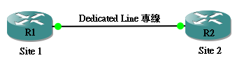
Frame Relay 是一个较经济的 WAN 配置办法。到底 Frame Relay 怎样帮我们节省成本呢?以下有一个例子,假设一间公司有两个办公室,最简单的方法就是用 Dedicated Line (专线) 把两个 Site 连起来。
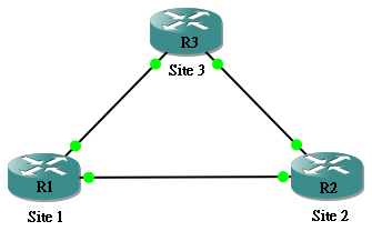
如果这家公司未来增加多一个 Site,就要再增加两条专线将其接通,但一条专线价值不菲,而且每个 Router 也要增加 Interface Port 亦增加了成本,除非钱并不是考虑因素,否则,专线显然并非理想的解决办法。
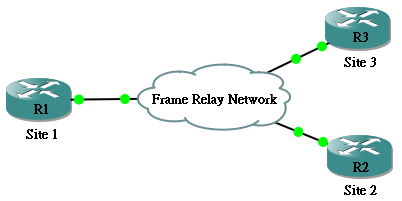
Frame Relay 的出现就是让我们可以透过 ISP 提供的 Frame Relay Network,连接不同的 Site 来建立 WAN 连线。ISP 用 Frame Relay Network 同时服务多个客户,价格方便当然比专线便宜,而且每个 Router 只需要一个 Interface,两者都可以在预算上省却成本。
DLCI
DLCI (Data Link Connection Identifier) 是一组让 Frame Relay Switch 阅读的地址,就好像 Ethernet 里面的 MAC Address 一样,让每一个 Frame 传到相应的目的地。而这组 DLCI 只会在 Local Router 使用,所以每只 Router 都有自己的 DLCI Mapping。要解释 DLCI,可以用乘飞机作一个比喻,如我们要乘飞机去外地,去到机场便要知道在那一个闸口上机,上了飞机几个小时後,到达目的地了,乘客就在另一个机场的某一个闸口下机,这个离开飞机的闸口号码跟原本上机的闸口号码并没有任可关系,号码通常会不同,也有很小的机会和上机时一样。DLCI 就像这个闸口的号码,每一个 Frame 在登上 Frame Relay Network 之前都要先放置一个 DLCI。到达 Frame Relay Network 的另一端,会变成另一个 DLCI 号码。
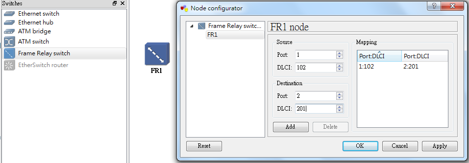
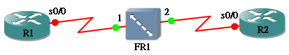
我们可以用 GNS3 里面内建的 Frame Relay Switch 来尝试作一个简单的 Frame Relay 实验。首先把 Frame Relay Switch 拉出来,然後按右键选 Configure 去设定 DLCI 值。以下图这个设定为例:即是说如果 DLCI 是 102 的 Frame 从 Port 1 进来,就把它改成 DLCI 201 送到 Port 2。留意这设定是双向的,即是说 DLCI 201 的 Frame 从 Port 2 进来,也会改成 DLCI 102 送到 Port 1。
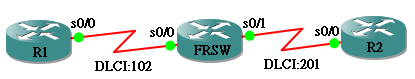
然後,把 R1 和 R2 与 Frame Relay Switch 连接如下图:
要设定这组 Frame Relay 步骤非常简单,全部在 Interface 里面完成:
- 设定 IP Address
- 输入 encapsulation frame-relay 来让 Interface 知道使用 frame-relay 协定
- 用 frame-relay interface-dlci <dlci> 设定 DLCI 号码,根据 Frame Relay Switch 的设定,R1 应该使用 102,而 R2 应该使用 201
以下是 R1 及 R2 的设定:
hostname R1
!
interface Serial0/0
 ip address 192.168.12.1 255.255.255.0
 encapsulation frame-relay
 serial restart-delay 0
 frame-relay interface-dlci 102
hostname R2
!
interface Serial0/0
 ip address 192.168.12.2 255.255.255.0
 encapsulation frame-relay
  serial restart-delay 0
  frame-relay interface-dlci 201
如果设定没问题的话,可以从 R1 Ping 到 R2,show frame-relay pvc 会见到有一条 PVC (Permenent Virtual Circuit) 正在 Active,而且有 Packets 在使用。
R1#ping 192.168.12.2

Type escape sequence to abort.
Sending 5, 100-byte ICMP Echos to 192.168.12.2, timeout is 2 seconds:
!!!!!
Success rate is 100 percent (5/5), round-trip min/avg/max = 12/34/68 ms
R1#
R1#show frame-relay pvc

PVC Statistics for interface Serial0/0 (Frame Relay DTE)

              Active     Inactive      Deleted       Static
  Local          1            0            0            0
  Switched       0            0            0            0
  Unused         0            0            0            0

DLCI = 102, DLCI USAGE = LOCAL, PVC STATUS = ACTIVE, INTERFACE = Serial0/0

  input pkts 6             output pkts 6            in bytes 554
  out bytes 554            dropped pkts 0           in pkts dropped 0
  out pkts dropped 0                out bytes dropped 0
  in FECN pkts 0           in BECN pkts 0           out FECN pkts 0
  out BECN pkts 0          in DE pkts 0             out DE pkts 0
  out bcast pkts 1         out bcast bytes 34
  5 minute input rate 0 bits/sec, 0 packets/sec
  5 minute output rate 0 bits/sec, 0 packets/sec
  pvc create time 00:09:07, last time pvc status changed 00:07:52
另外,show frame-relay map 可以看到 IP 与 DLCI 的 mapping,情况就像在 Ethernet 看 ARP Table 一样。在这个例子中 mapping 是自动产生的 (dynamic),因为 interface default 使用了 Inverse ARP,关於自动不自动的问题,然在先记一下就好,稍後我们才会尝试手动设定 (static)。
R1#show frame-relay map
 Serial0/0 (up): ip 192.168.12.2 dlci 102(0x66,0x1860), dynamic,
               broadcast,
               CISCO, status defined, active
Frame Relay Switching
刚才我们用 GNS3 的 Frame Relay Switch 来做实验,其实 Cisco Router 也支缓 Frame Relay Switching,接下来我们把原来的 Frame Relay Switch 换成一只 Router,看看怎样用 Router 来执行 Frame Relay Switching。基本上 R1 及 R2 的设定都没有更改,要学习的只是怎样设定 FRSW。
再设定之前请先学习两个大名:DTE 和 DCE。
DTE (Data Terminal Equipment)
DTE,全名是Data Terminal Equipment。一般而言,DTE 代表着用户端的设备,例如上图的 Frame Relay Network 中,R1 和 R2 就是 DTE。 Interface 预设设定成 DTE,所以 R1 和 R2 设定不用更改。
DCE (Data Circuit-terminating Equipment)
DCE,全名是Data Circuit-terminating Equipment。DCE 的用途是在网路内提供 Clocking 和Switching 服务,以及负责在 WAN 传递资料。一般用来形容 ISP 的设备,现在 FRSW 就是 DCE 了。由於 Interface 预设设定是 DTE,所以 FRSW 的 Interface 需要更改成 DCE 设定。
设定 FRSW 有以下几个步骤:
- 使用 frame-relay switching 开启 Router 的 Frame Relay Switch 功能
- 在 Interface 使用 encapsulation frame-relay 来让 Interface 知道使用 frame-relay 协定
- 在 Interface 使用 frame-relay intf-type dce 把 Interface 设成 DCE
- 用 frame-relay route <dlci> interface <interface> <dlci> 来设定 Frame Relay Route。所谓 Frame Relay Route 其实就像之前设定 frame relay switch 的示范,让 Router 知道 Frame 「上机和下机」的安排。
在 serial0/0 所设定的 frame-relay route 意思是:从 Serial 0/0 收到 DLCI 102 的 Frame 就传到 Serial 0/1 而且把 DLCI 改为 201,在 Serial 0/1 则刚好相反。所以说,和之前设定图像化的 Frame Relay Switch 是一样的,只不过改成指令而已。
hostname FRSW
!
frame-relay switching
!
interface Serial0/0
 no ip address
 encapsulation frame-relay
 frame-relay intf-type dce
 frame-relay route 102 interface Serial0/1 201
!
interface Serial0/1
 no ip address
 encapsulation frame-relay
 frame-relay intf-type dce
 frame-relay route 201 interface Serial0/0 102
最後确定一下是否已经通行。
R1#ping 192.168.12.2

Type escape sequence to abort.
Sending 5, 100-byte ICMP Echos to 192.168.12.2, timeout is 2 seconds:
!!!!!
Success rate is 100 percent (5/5), round-trip min/avg/max = 44/64/120 ms
现在我们再玩大一点,如上面的例子所示,客户向 ISP 购买了 Frame Relay 服务之後,就会接上 ISP 的 Frame Relay Switch Cloud,在这个 Cloud 当中当然不会只有一只 Frame Relay Switch,如果有超过一只的话又要怎样设定呢?我们看看以下的例子:
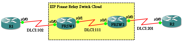
有两个地方要注意的:
- 两个 FRSW 中间多了一个 DLCI 111,设定 Route 时需要留意
- FRSW1 连接 FRSW2 的 Interface 不是 DCE,也不是 DTE,要使用 NNI
hostname FRSW1
!
frame-relay switching
!
interface Serial0/0
 no ip address
 encapsulation frame-relay
 serial restart-delay 0
 frame-relay intf-type dce
 frame-relay route 102 interface Serial0/1 111
!
interface Serial0/1
 no ip address
 encapsulation frame-relay
 serial restart-delay 0
 frame-relay intf-type nni
 frame-relay route 111 interface Serial0/0 102
hostname FRSW2
!
interface Serial0/0
 no ip address
 encapsulation frame-relay
 serial restart-delay 0
 frame-relay intf-type dce
 frame-relay route 201 interface Serial0/1 111
!
interface Serial0/1
 no ip address
 encapsulation frame-relay
 serial restart-delay 0
 frame-relay intf-type nni
 frame-relay route 111 interface Serial0/0 201
所以,无论 Frame Relay Switch Cloud 里面有多少只 Frame Relay Switch,设定都是大同小异的,目的都是为 Frame 「预设好行走的路径」。
Multipoint Frame Relay
接下来我们体验一下如何把多个 Site 透过 Frame Relay 连接,一般来说,购买 ISP 的 Frame Relay 服务是按 Connection 的数量来付款的,举例:如果你有 n 个 Site 要做 Fully Mesh Topology 的连接,你就要购买 n(n-1) / 2 条 Connection,这是一个不可能的任务,除非钱不是问题吧!所以,我们多数会用 Hub And Spoke Topology,意思是只把所有 Remote Site 连接到 Head Quarter(HQ)。
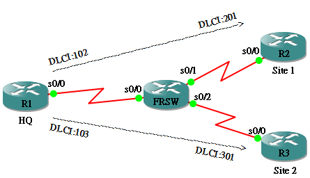
要设定上图的网络,需注意以下几点:
- R1 要到达 R2 和 R3 分别要使用不同的 DLCI,不能用 frame-relay interface-dlci <dlci> 来设定 DLCI 了,我们要用 frame-relay map ip <ip> <dlci> 逐一为不同的 IP 设定。
- 我们已经不能用 Inverse ARP 来取得 DLCI 和 IP 的 Mapping 了,所以 R2 和 R3 也要用 frame-relay map ip <ip> <dlci> 来设定
- R2 要透过 R1 到达 R3,因此除了 R1 的 Mapping 之外,也要为 R3 的 IP 额外增加一个 Mapping,同样地,在 R3 的情况也一样,要为 R2 的 IP 做 Mapping
- FRSW 要为每个 DLCI 做 Route 设定
hostname R1
!
interface Serial0/0
 ip address 192.168.123.1 255.255.255.0
 encapsulation frame-relay
 frame-relay map ip 192.168.123.2 102
 frame-relay map ip 192.168.123.3 103
hostname R2
!
interface Serial0/0
 ip address 192.168.123.2 255.255.255.0
 encapsulation frame-relay
 frame-relay map ip 192.168.123.1 201
 frame-relay map ip 192.168.123.3 201
hostname R3
 !
 interface Serial0/0
  ip address 192.168.123.3 255.255.255.0
  encapsulation frame-relay
  frame-relay map ip 192.168.123.1 301
  frame-relay map ip 192.168.123.2 301
hostname FWSW
!
frame-relay switching
!
interface Serial0/0
 no ip address
 encapsulation frame-relay
 frame-relay intf-type dce
 frame-relay route 102 interface Serial0/1 201
 frame-relay route 103 interface Serial0/2 301
!
interface Serial0/1
 no ip address
 encapsulation frame-relay
 frame-relay intf-type dce
 frame-relay route 201 interface Serial0/0 102
!
interface Serial0/2
 no ip address
 encapsulation frame-relay
 frame-relay intf-type dce
 frame-relay route 301 interface Serial0/0 103
最後确认一下从 R3 可以 Ping 通 R1 及 R2,而且试试 Traceroute R2 会发现是经过 R1 再到达 R2。
R3#ping 192.168.123.1

Type escape sequence to abort.
Sending 5, 100-byte ICMP Echos to 192.168.123.1, timeout is 2 seconds:
!!!!!
Success rate is 100 percent (5/5), round-trip min/avg/max = 28/48/84 ms
R3#
R3#ping 192.168.123.2

Type escape sequence to abort.
Sending 5, 100-byte ICMP Echos to 192.168.123.2, timeout is 2 seconds:
!!!!!
Success rate is 100 percent (5/5), round-trip min/avg/max = 68/81/104 ms
R3#
R3#traceroute 192.168.123.2

Type escape sequence to abort.
Tracing the route to 192.168.123.2

  1 192.168.123.1 108 msec 80 msec 36 msec
  2 192.168.123.2 168 msec 120 msec 72 msec
Multipoint Frame Relay 虽然设定上简单,但对某些 Routing Protocol 会产生一些问题。首先,Multipoint Frame Relay 预设是不会 Forward Broadcast 的,也不会 Forward Multicast,所以如果要靠 Multicast 来连接的 Routing Protocol 会预到障碍。继续使用刚才的 Topology ,我们用 EIGRP 来做例子:
三只 Router 都设定好 EIGRP:
hostname R1
!
router eigrp 1
 network 192.168.123.0
hostname R2
!
router eigrp 1
 network 192.168.123.0
hostname R3
!
router eigrp 1
 network 192.168.123.0
但一直无法发现 Neighbor:
R1#show ip eigrp 1 neighbors
 IP-EIGRP neighbors for process 1
因为 EIGRP 是用 Multicast 来传送 Hello Message 的,Frame Relay 不送 Multicast 就无法成 Neighbor,解决方法是在使用 frame-relay map 时加入 broadcast 这个 keyword,这样 Frame Relay 就能传送 Broadcast 和 Multicast 了。
hostname R1
!
interface Serial0/0
 ip address 192.168.123.1 255.255.255.0
 encapsulation frame-relay
 frame-relay map ip 192.168.123.2 102 broadcast
 frame-relay map ip 192.168.123.3 103 broadcast
hostname R2
!
interface Serial0/0
 ip address 192.168.123.2 255.255.255.0
 encapsulation frame-relay
 frame-relay map ip 192.168.123.1 201 broadcast
 frame-relay map ip 192.168.123.3 201 broadcast
hostname R3
!
interface Serial0/0
 ip address 192.168.123.3 255.255.255.0
 encapsulation frame-relay
 frame-relay map ip 192.168.123.1 301 broadcast
 frame-relay map ip 192.168.123.2 301 broadcast
这样才能成功成为 Neighbors:
R1#show ip eigrp 1 neighbors
IP-EIGRP neighbors for process 1
H   Address                 Interface       Hold Uptime   SRTT   RTO  Q  Seq
                                             (sec)         (ms)       Cnt Num
1   192.168.123.3           Se0/0            160 00:12:33   77   462  0  5
0   192.168.123.2           Se0/0            165 00:12:36   64   384  0  5
Multipoint 对 Routing Protocol 的另一个冲击是 Split Horizon 问题。使用 Distance Vector 的 Routing Protocol 预设会开启 Split Horizon 保护,使由某 Interface 入来的 Route 资讯不会於同一个 Interface 散播出去,防止 Route Loop。这遇到 Multipoint Frame Relay 就会发生了问题。
做个简单实验,在 R2 增加了一个 Loopback,IP 为 2.2.2.2,透过 EIGRP 发布此网段。
hostname R2
!
interface Loopback0
 ip address 2.2.2.2 255.255.255.255
!
router eigrp 1
 network 2.2.2.2 0.0.0.0
 network 192.168.123.0
R1 收到了这 Route 但 R3 却一直接收不到:
R1#show ip eigrp topology
IP-EIGRP Topology Table for AS(1)/ID(192.168.123.1)

Codes: P - Passive, A - Active, U - Update, Q - Query, R - Reply,
       r - reply Status, s - sia Status

P 2.0.0.0/8, 1 successors, FD is 2297856
        via 192.168.123.2 (2297856/128256), Serial0/0
P 192.168.123.0/24, 1 successors, FD is 2169856
        via Connected, Serial0/0
R3#show ip eigrp topology
IP-EIGRP Topology Table for AS(1)/ID(192.168.123.3)

Codes: P - Passive, A - Active, U - Update, Q - Query, R - Reply,
       r - reply Status, s - sia Status

P 192.168.123.0/24, 1 successors, FD is 2169856
        via Connected, Serial0/0
原因是 R1 从 Serial 0/0 收到 2.0.0.0/8 之後,因为 Split Horizon 的关系,不能在 Serial 0/0 传给 R3,解决办法是在 R1 关掉 Split Horizon。
R1(config-if)#no ip split-horizon eigrp 1
问题就解决了:
R3#show ip eigrp topology
IP-EIGRP Topology Table for AS(1)/ID(192.168.123.3)

Codes: P - Passive, A - Active, U - Update, Q - Query, R - Reply,
       r - reply Status, s - sia Status

P 2.0.0.0/8, 1 successors, FD is 2809856
        via 192.168.123.1 (2809856/2297856), Serial0/0
P 192.168.123.0/24, 1 successors, FD is 2169856
        via Connected, Serial0/0
R3#
R3#ping 2.2.2.2

Type escape sequence to abort.
Sending 5, 100-byte ICMP Echos to 2.2.2.2, timeout is 2 seconds:
!!!!!
Success rate is 100 percent (5/5), round-trip min/avg/max = 64/92/136 ms
Point to Point Sub-interface
另一个建立 Frame Relay 的方法是使用 Point to Point Sub-Interface。Sub-Interface 意思是把一个 Interface 分成两个或以上,例如:Serial 0/0 分成 Serial 0/0.1 和 Serial 0/0.2 来连接两个不同的网段,留意由於 Sub-Interface 不能使用相同的网段,因此在 IP Address 的配置上需要有一点转变。
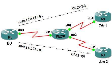
设定上图的网络要点如下:
- 把 R1 的 Serial 0/0.1 与 R2 的 Serial 0/0 放在同一网段,把 R1 的 Serial 0/0.2 与 R3 的 Serial 0/0 放在另一个网段
- 用 frame-relay interface-dlci <dlci> 设定 DLCI 号码
hostname R1
!
interface Serial0/0
 no ip address
 encapsulation frame-relay
 serial restart-delay 0
!
interface Serial0/0.1 point-to-point
 ip address 192.168.12.1 255.255.255.0
 frame-relay interface-dlci 102
!
interface Serial0/0.2 point-to-point
 ip address 192.168.13.1 255.255.255.0
 frame-relay interface-dlci 103
hostname R2
!
interface Serial0/0
 ip address 192.168.12.2 255.255.255.0
 encapsulation frame-relay
 serial restart-delay 0
 frame-relay interface-dlci 201
hostname R3
!
interface Serial0/0
 ip address 192.168.13.3 255.255.255.0
 encapsulation frame-relay
 serial restart-delay 0
 frame-relay interface-dlci 301
完成设定後,基本上各 Router 都能透过 Inverse ARP 找到对方的 Mapping,R1 可以 Ping 通 R2 和 R3。
R1#show frame-relay map
Serial0/0.1 (up): point-to-point dlci, dlci 102(0x66,0x1860), broadcast
          status defined, active
Serial0/0.2 (up): point-to-point dlci, dlci 103(0x67,0x1870), broadcast
          status defined, active
R1#
R1#ping 192.168.12.2

Type escape sequence to abort.
Sending 5, 100-byte ICMP Echos to 192.168.12.2, timeout is 2 seconds:
!!!!!
Success rate is 100 percent (5/5), round-trip min/avg/max = 20/63/112 ms
R1#
R1#ping 192.168.13.3

Type escape sequence to abort.
Sending 5, 100-byte ICMP Echos to 192.168.13.3, timeout is 2 seconds:
!!!!!
Success rate is 100 percent (5/5), round-trip min/avg/max = 32/49/80 ms
但问题出现了,你会发现在 R2 不能 Ping R3。当然了!因为我们把 R2 和 R3 放在不同的网段嘛,所以我们要靠 Routing Protocol 来交换大家的 Route 啦!例如用 EIGRP。
hostanme R1
!
router eigrp 1
 network 192.168.12.0
 network 192.168.13.0
 auto-summary
hostname R2
!
router eigrp 1
 network 192.168.12.0
 auto-summary
hostname R3
!
router eigrp 1
 network 192.168.13.0
 auto-summary
与 Multipoint 不同,Point to point Sub-Interface 本来已支缓 broadcast,所以在建立 Neighbor 方面不成问题,另外,因为 Sub-Interface 在 Routing Protocol 的角度看来是两个不同的 Interface,也不存在 Split Horizon 导致的问题,所以在 Routing Protocol 设定方面就简单得多。现在从 R2 应该可以 Ping 到 R3 了!
R2#ping 192.168.13.3

Type escape sequence to abort.
Sending 5, 100-byte ICMP Echos to 192.168.13.3, timeout is 2 seconds:
!!!!!
Success rate is 100 percent (5/5), round-trip min/avg/max = 68/84/108 ms
相關主題
Jan Ho 2021-07-22
Posted In: Layer 2 网络技术
发表回复