目錄
前言
Policy Based Routing (PBR) 名字好像有点深奥,其实说穿了只不过是改改 Next Hop IP 让我们可以对 Routing Table 的结果作出干扰,控制某些 Traffic 的路由方向。本篇假设读者已经了解路由判断和 EIGRP 等理论,如不肯定可以先温习一下。
实验基本设定
为了测试 PBR,先设定好以下网络,假设 R1 是公司的 WAN Link Router,分别连接 ISP1 (R2) 和 ISP2 (R3),所有 Router 执行 EIGRP。
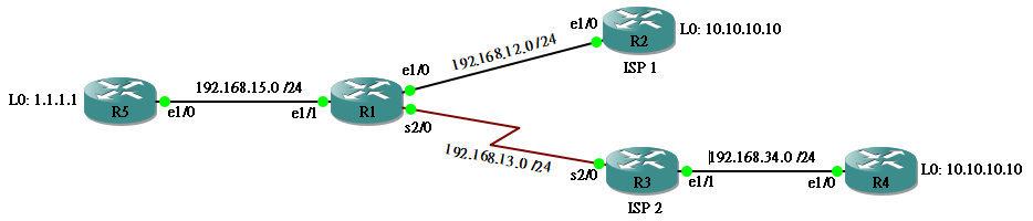
R1 会收到分别由 R2 和 R3 传来 10.10.10.10/32 的 Route,即是说 R1 无论用 ISP1 或 ISP2 都能够到达 10.10.10.10。
R1#show ip eigrp topology all-links
EIGRP-IPv4 Topology Table for AS(1)/ID(192.168.15.1)
Codes: P - Passive, A - Active, U - Update, Q - Query, R - Reply,
       r - reply Status, s - sia Status

P 10.10.10.10/32, 1 successors, FD is 409600, serno 9
        via 192.168.12.2 (409600/128256), Ethernet1/0
        via 192.168.13.3 (2323456/409600), Serial2/0
P 192.168.34.0/24, 1 successors, FD is 2195456, serno 12
        via 192.168.13.3 (2195456/281600), Serial2/0
P 192.168.12.0/24, 1 successors, FD is 281600, serno 1
        via Connected, Ethernet1/0
P 192.168.13.0/24, 1 successors, FD is 2169856, serno 11
        via Connected, Serial2/0
P 192.168.15.0/24, 1 successors, FD is 281600, serno 13
        via Connected, Ethernet1/1
P 1.1.1.1/32, 1 successors, FD is 409600, serno 14
        via 192.168.15.5 (409600/128256), Ethernet1/1
当然 R1 选了 Next Hop 为 192.168.12.2 这条 Route,因为 Metric 较小。
R1#show ip route eigrp
Codes: L - local, C - connected, S - static, R - RIP, M - mobile, B - BGP
       D - EIGRP, EX - EIGRP external, O - OSPF, IA - OSPF inter area
       N1 - OSPF NSSA external type 1, N2 - OSPF NSSA external type 2
       E1 - OSPF external type 1, E2 - OSPF external type 2
       i - IS-IS, su - IS-IS summary, L1 - IS-IS level-1, L2 - IS-IS level-2
       ia - IS-IS inter area, * - candidate default, U - per-user static route
       o - ODR, P - periodic downloaded static route, H - NHRP, l - LISP
       + - replicated route, % - next hop override

Gateway of last resort is not set

      1.0.0.0/32 is subnetted, 1 subnets
D        1.1.1.1 [90/409600] via 192.168.15.5, 00:16:08, Ethernet1/1
      10.0.0.0/32 is subnetted, 1 subnets
D        10.10.10.10 [90/409600] via 192.168.12.2, 00:03:38, Ethernet1/0
D 192.168.34.0/24 [90/2195456] via 192.168.13.3, 00:19:26, Serial2/0
然而,我们故意在 R3 加入一条 Distribute List 来阻挡 10.10.10.10/32 发放至 R1,迫使所有要到 10.10.10.10/32 的 Traffic 只有 R5 > R1 > R2 这条路径。
R3(config)#ip prefix-list DENY_10 deny 10.10.10.10/32
R3(config)#ip prefix-list DENY_10 permit 0.0.0.0/0 le 32
R3(config)#router eigrp 1
R3(config-router)#distribute-list prefix DENY_10 out
所以,R1 知道只有 192.168.12.2 可以到达 10.10.10.10/32。
R1#show ip eigrp topology all-links
EIGRP-IPv4 Topology Table for AS(1)/ID(192.168.15.1)
Codes: P - Passive, A - Active, U - Update, Q - Query, R - Reply,
       r - reply Status, s - sia Status

P 10.10.10.10/32, 1 successors, FD is 409600, serno 9
        via 192.168.12.2 (409600/128256), Ethernet1/0
P 192.168.31.0/24, 1 successors, FD is 281600, serno 23
        via Connected, Ethernet1/7
P 192.168.12.0/24, 1 successors, FD is 281600, serno 1
        via Connected, Ethernet1/0
P 192.168.15.0/24, 1 successors, FD is 281600, serno 13
        via Connected, Ethernet1/1
P 1.1.1.1/32, 1 successors, FD is 409600, serno 14
        via 192.168.15.5 (409600/128256), Ethernet1/1
所以,在 R5 Traceroute 10.10.10.10 的话,Packet 会走 R5 > R1 > R2 这条路径。到此应该没有问题吧?如无法理解,请先到 EIGRP 练功後再来挑战。
Set Ip Next-hop
PBR 第一式是 Set Ip Next-hop,我们可以强迫从 R5 Source 1.1.1.1 到 Destination 10.10.10.10 的 Traffic 走 R5 > R1 > R3 > R4,其馀的 Traffic 却走原来的 R5 > R1 > R2,这就是所谓的 Policy。
基本设定
设定上不会复杂,先在 R1 用 Extended Access List 把想要的 Traffic 抓出来。
R1(config)#ip access-list extended PBR_TRAFFIC
R1(config-ext-nacl)#permit ip host 1.1.1.1 host 10.10.10.10
然後用 Route Map 去改变 Next Hop IP。
R1(config)#route-map PBR
R1(config-route-map)#match ip address PBR_TRAFFIC
R1(config-route-map)#set ip next-hop 192.168.13.3
最後把这条 Route Map 放到 e1/1,即 Traffic 流进的方向。
R1(config)#int ethernet 1/1
R1(config-if)#ip policy route-map PBR
现在,从 R5 1.1.1.1 到 10.10.10.10 的 Traffic 就走 R5 > R1 > R3 > R4 了。
R5#traceroute 10.10.10.10 source 1.1.1.1
Type escape sequence to abort.
Tracing the route to 10.10.10.10
VRF info: (vrf in name/id, vrf out name/id)
  1 192.168.15.1 48 msec 24 msec 20 msec
  2 192.168.13.3 40 msec 40 msec 32 msec
  3 192.168.34.4 52 msec 40 msec 40 msec
其他 Traffic 却走原本的 R5 > R1 > R2。(Traceroute 不设定 Source,Router 预设使用 Outbound Interface 作为 Source,即 e1/0 的 192.168.15.5。)
R5#traceroute 10.10.10.10
Type escape sequence to abort.
Tracing the route to 10.10.10.10
VRF info: (vrf in name/id, vrf out name/id)
  1 192.168.15.1 12 msec 20 msec 20 msec
  2 192.168.12.2 28 msec 32 msec 32 msec
注意,使用这个方法,Next Hop IP 必需是存在於 Directly Connected 的 Network 之中,否则 PBR 设定不会有效。
例如:把 R3 的 S2/0 shutdown。
R3(config)#int serial 2/0
R3(config-if)#shutdown
R1 Route Table 的 192.168.13.0/24 这个 Connected Network 就消失了,造成 set ip next hop 无效。
R1#show ip route
Codes: L - local, C - connected, S - static, R - RIP, M - mobile, B - BGP
       D - EIGRP, EX - EIGRP external, O - OSPF, IA - OSPF inter area
       N1 - OSPF NSSA external type 1, N2 - OSPF NSSA external type 2
       E1 - OSPF external type 1, E2 - OSPF external type 2
       i - IS-IS, su - IS-IS summary, L1 - IS-IS level-1, L2 - IS-IS level-2
       ia - IS-IS inter area, * - candidate default, U - per-user static route
       o - ODR, P - periodic downloaded static route, H - NHRP, l - LISP
       + - replicated route, % - next hop override

Gateway of last resort is not set

      1.0.0.0/32 is subnetted, 1 subnets
D        1.1.1.1 [90/409600] via 192.168.15.5, 00:46:36, Ethernet1/1
      10.0.0.0/32 is subnetted, 1 subnets
D        10.10.10.10 [90/409600] via 192.168.12.2, 00:05:40, Ethernet1/0
      192.168.12.0/24 is variably subnetted, 2 subnets, 2 masks
C        192.168.12.0/24 is directly connected, Ethernet1/0
L        192.168.12.1/32 is directly connected, Ethernet1/0
      192.168.15.0/24 is variably subnetted, 2 subnets, 2 masks
C        192.168.15.0/24 is directly connected, Ethernet1/1
L        192.168.15.1/32 is directly connected, Ethernet1/1
Traffic 就会跟原本路经走。
R5#traceroute 10.10.10.10 source 1.1.1.1
Type escape sequence to abort.
Tracing the route to 10.10.10.10
VRF info: (vrf in name/id, vrf out name/id)
  1 192.168.15.1 20 msec 20 msec 20 msec
  2 192.168.12.2 28 msec 28 msec 20 msec
轻轻一提,如果 set ip next hop 设定了两组 IP 或以上,则 Router 会先检查第一组 IP 是否存在於 Connected Network,有则使用,无则检查下一组,如此类推。
Verify Availability
有时 Interface 是 UP,Route Table 有 Connected Network 了,却因为其他原因无法传 Data。如果想稳当一点,我们可以加一句 set ip next-hop verify-availability,这样 R1 就会监察 R3 的 CDP 状态,如果收不到 CDP 就算 Interface UP 也不会发生 PBR。
route-map PBR permit 10
 match ip address PBR_TRAFFIC
 set ip next-hop 192.168.13.3
 set ip next-hop verify-availability
IP SLA Tracking
假设 R1 与 R3 之间并非直接连上,而是经过 Switch,R1 不能用 CDP 监察也无法感知 R3 的 Port 是 UP 还是 DOWN。如果 R3 那边 DOWN 了,PBR 却继续执行,Packet 就石沉大海无法到达。如遇这情况我们可以使用 IP SLA Tracking。
首先建立 SLA,如不清楚 SLA 原理,请看这篇文章。IOS Version 不同,指令设定上会有少许差异。
R1(config)#ip sla 1
R1(config-ip-sla)#icmp-echo 192.168.13.3
R1(config-ip-sla-echo)#frequency 5
R1(config-ip-sla-echo)#timeout 5000
R1(config-ip-sla-echo)#threshold 100
R1(config-ip-sla-echo)#exit
R1(config)#ip sla schedule 1 life forever start-time now
然後使用 sla 1 用作 track 1,并加进 Route Map 就可以了。
R1(config)#track 1 ip sla 1 reachability
R1(config)#route-map PBR permit 10
R1(config-route-map)#match ip address PBR_TRAFFIC
R1(config-route-map)#set ip next-hop verify-availability 192.168.13.3 1 track 1
用 show route-map 确认一下,现时 tracking 是 [up] 的,即 SLA 1 状态正常,亦即是 192.168.13.3 可以 Ping 通。
R1#show route-map
route-map PBR, permit, sequence 10
  Match clauses:
    ip address (access-lists): PBR_TRAFFIC
  Set clauses:
     ip next-hop verify-availability 192.168.13.3 1 track 1  [up]
  Policy routing matches: 129 packets, 7740 bytes
所以 PBR 是发挥作用的。
R5#traceroute 10.10.10.10 source 1.1.1.1
Type escape sequence to abort.
Tracing the route to 10.10.10.10
VRF info: (vrf in name/id, vrf out name/id)
  1 192.168.15.1 52 msec 40 msec 20 msec
  2 192.168.13.3 40 msec 20 msec 20 msec
  3 192.168.34.4 32 msec 32 msec 28 msec
如果在 R3 把 S2/0 Shutdown,R1 的 Tracking 就 down 了。
R1#show route-map
route-map PBR, permit, sequence 10
  Match clauses:
    ip address (access-lists): PBR_TRAFFIC
  Set clauses:
     ip next-hop verify-availability 192.168.13.3 1 track 1  [down]
  Policy routing matches: 159 packets, 9540 bytes
所以 PBR 不会生效。
R5#traceroute 10.10.10.10 source 1.1.1.1
Type escape sequence to abort.
Tracing the route to 10.10.10.10
VRF info: (vrf in name/id, vrf out name/id)
  1 192.168.15.1 20 msec 20 msec 12 msec
  2 192.168.12.2 20 msec 20 msec 20 msec
Set Ip Next-hop Recursive
刚才说过如果用 Set Ip Next-hop ,Next Hop 必需是 Connected Network,PBR才会生效。如果有需要用非 Connected Network 的 Interface 做 Next Hop 的话,可以用招式二 Set Ip Next-hop Recursive。例如:在刚才的网络中想把 Next Hop 指向 192.168.34.4,设定如下:
R1(config)#route-map PBR
R1(config-route-map)#match ip address PBR_TRAFFIC
R1(config-route-map)#set ip next-hop recursive 192.168.34.4
Set Ip Default Next-hop
PBR 招式三 Set Ip Default Next-hop,这句指令让人有点混淆,它的意思是说 PBR 只用作後备路径,Router 会预设使用 Route Table 的 Route 到达目的地。除非 Route Table 找不到纪录时才使用 PBR。
R1(config)#route-map PBR
R1(config-route-map)#match ip address PBR_TRAFFIC
R1(config-route-map)#set ip default next-hop 192.168.13.3
由於 R1 的 Route Table 有 10.10.10.10/32 存在。
R1#show ip route 10.10.10.10
Routing entry for 10.10.10.10/32
  Known via "eigrp 1", distance 90, metric 409600, type internal
  Redistributing via eigrp 1
  Last update from 192.168.12.2 on Ethernet1/0, 1d15h ago
  Routing Descriptor Blocks:
  * 192.168.12.2, from 192.168.12.2, 1d15h ago, via Ethernet1/0
      Route metric is 409600, traffic share count is 1
      Total delay is 6000 microseconds, minimum bandwidth is 10000 Kbit
      Reliability 255/255, minimum MTU 1500 bytes
      Loading 1/255, Hops 1
这时侯就算附合 Policy 的 Traffic 通过,R1 仍会使用正常路径 R5 > R1 > R2。
R5#traceroute 10.10.10.10 source 1.1.1.1
Type escape sequence to abort.
Tracing the route to 10.10.10.10
VRF info: (vrf in name/id, vrf out name/id)
  1 192.168.15.1 20 msec 20 msec 20 msec
  2 192.168.12.2 20 msec 20 msec 20 msec
除非把 Route 杀掉,例如 Shutdown R2 的 e1/0。
R2(config)#int ethernet 1/0
R2(config-if)#shutdown
R1 的 10.10.10.10/32 Route 消失了。
R1#show ip route 10.10.10.10
% Network not in table
於是 PBR 生效。
R5#traceroute 10.10.10.10 source 1.1.1.1
Type escape sequence to abort.
Tracing the route to 10.10.10.10
VRF info: (vrf in name/id, vrf out name/id)
  1 192.168.15.1 20 msec 12 msec 8 msec
  2 192.168.13.3 64 msec 40 msec 28 msec
  3 192.168.34.4 72 msec 48 msec 52 msec
Set Interface
第四式 Set Interface 这个指令比较单纯,就是把 Next Hop 直接指向一 Outbound Interface (需为 Point to Point Interface)。例如:在 R1 不使用 IP 192.168.13.3 作为 Next Hop,取而代之的是使用 Interface Serial 2/0。
R1(config)#route-map PBR
R1(config-route-map)#match ip address PBR_TRAFFIC
R1(config-route-map)#set interface serial 2/0
Set Default Interface
最後一招是与 set ip default next-Hop 有相同功效的 set default interface,就是当 Route table 的 Route 失去时才使用 PBR 指向 Interface。
R1(config)#route-map PBR
R1(config-route-map)#match ip address PBR_TRAFFIC
R1(config-route-map)#set default interface serial 2/0
PBR 的处理次序
当以上 PBR 设定同时存在於同一 Route Map 时,Router 会按以下优先次序执行。
- set ip next hop
- set ip next hop recursive
- set ip default next hop
- set interface
- set default interface
举例:set ip next hop,set ip default next hop 与 set interface 同时存在,只有 set ip next hop 生效。
相關主題
Jan Ho 2021-07-22
Posted In: Layer 3 网络技术
发表回复